

It is very exciting to see something floating in the air or free space that is exactly what an anti-gravity project is about. The object (basically a small piece of paper or thermocol) is placed between two ultrasonic transducers which generate acoustic sound waves. The object floats in the air because of these waves which seem to be of anti-gravity. This is not only a cool looking Arduino levitation project, but it also has many practical applications. Researchers are working on Ultrasonic Robotic Grippers, which works very similar to this, and these grippers can be useful in moving objects without touching them.
Component Required
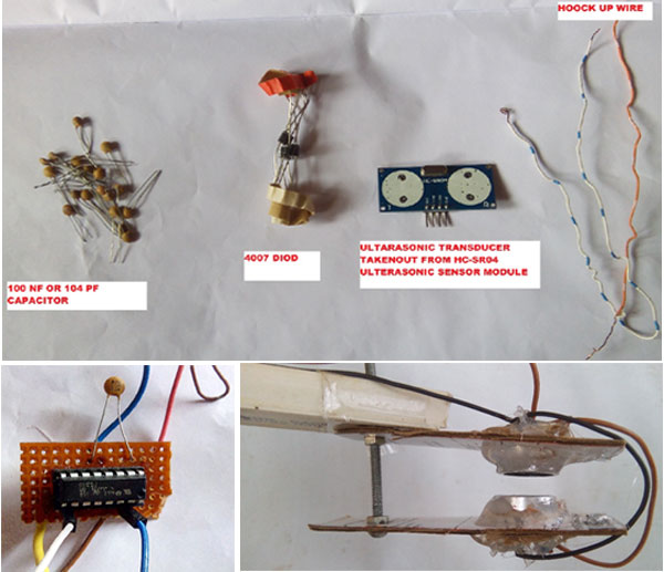
- Arduino Uno / Arduino Nano ATMEGA328P
- Ultrasonic Module HC-SR04
- IC or L239d H-Bridge Module L239D
- Vero Board Dotted Vero
- Diode 4007
- Capacitor (PF) 104
Additional Requirement for 8v To 12v Power Supply
- Voltage Regulator LM 7809
- Led Driver Power Supply 12V 2Amp
Additional Material: Some hookup wire, male header, female to female jumper wire
Ultrasonic Levitation Circuit Diagram
The complete Arduino Levitation circuit is shown below and the working principle of the circuit is very simple. The main component of this project is an Arduino, L239D motor driving IC, and ultrasonic transducer collected from the ultrasonic sensor module HCSR04. Generally, the ultrasonic sensor transmits an acoustic wave of a frequency signal between 25khz to 50 kHz, and in this project, we are using HCSR04 ultrasonic transducer. We have previously built many ultrasonic sensors projects, in which the HCSR04 is primarily used to measure distance. In this project, we have soldered out the transducer out from the module.

According to the datasheet, this ultrasonic transducer’s working frequency is 40 kHz. So, the purpose of using Arduino and this small piece of code is to generate a 40KHz high-frequency oscillation signal for my ultrasonic sensor or transducer and this pulse is applied to the input of duel motor driver IC L239D (Pin 2 & 6 from Arduino A0 & A1 pins) to drive the ultrasonic transducer. Finally, we apply this high-frequency 40KHz oscillation signal along with driving voltage through driving IC (typically 8 to12 voltage given on the 8th pin of the L239D IC, Vcc2) on the ultrasonic transducer. As a result of which ultrasonic transducer produces acoustic sound waves. We placed two transducers face to face in the opposite direction in such a manner that some space is left between them. Acoustic sound waves travel between two transducers and allow the object to float.
Please note that L293D has dual voltage input, one is to power the IC itself, which is powered from Arduino 5v in this project and another Vcc2 (8th) applied to output component driving voltage and this VCC pin can accept up to 36v. This IC has 2 Enable pins, 4 input-output pins, 4 ground pins. The concept of using this IC comes from the concept of using a microcontroller and this chip where we can change the direction and speed of 2 motors individually by just providing a logical or digital signal from the microcontroller.
In this circuit, we use only two inputs of the IC L293D, input pin 1 (2), and input pin 2 (7). To enable these two pins, we must keep IC Enable PIN 1 high, so we shot this pin to IC pin 16 which is input Vcc 1, to know more, please follow the L293D Datasheet.
The use of a 100nf capacitor is optional for just hold the IC power and as a power supply, we use a 12V 2Amp LED driver, then drop the voltage to 9v using Voltage regulator IC LM7809 and supply to 8th pin of L139D with common grounds. According to the Arduino, Cc, and Arduino forum, Arduino UNO board support 7 to 12 volts of input, but it's safer to put 9V Max.
Programming Arduino for Ultrasonic Levitation
The coding is very simple, just of few lines. Using this little code with the help of a timer and interrupt functions, we are making high or low (0 / 1) and generating an oscillating signal of 40Khz to Arduino A0 and A1 output pins.
First, start with a phase shift array.
byte TP = 0b10101010;
And every second port receives this opposite signal. After that under the void setup, we define all the analog ports as an output using this line of code.
DDRC = 0b11111111;
Then we initialize the timer 1 and disable all the interrupt to set as zero.
By this code,
noInterrupts();
  TCCR1A = 0;
  TCCR1B = 0;
  TCNT1  = 0;
Then, timer one is configured to trigger a compare interrupt clock at 80KHZ. Arduino runs at 16000000 MHZ ÷ 200 = 80,000 kHz square waves are generated using this function.
OCR1A = 200;TCCR1B |=
(1 << WGM12);
TCCR1B |= (1 << CS10);
After that, this line activates, compare timer interrupt.
TIMSK1 |= (1 << OCIE1A);
And finally, activate interrupt using this piece of code.
interrupts();
Each interrupt reverses the state of the analog ports, this turns 80 kHz square wave signal into a full-wave cycling signal at 40Khz. And then we send the value to Arduino output A0 and A1 port.
ISR(TIMER1_COMPA_vect)
{
  PORTC = TP;
  TP = ~TP;   // Invert TP for the next run
}
And there is nothing to put or needed to run under the loops.
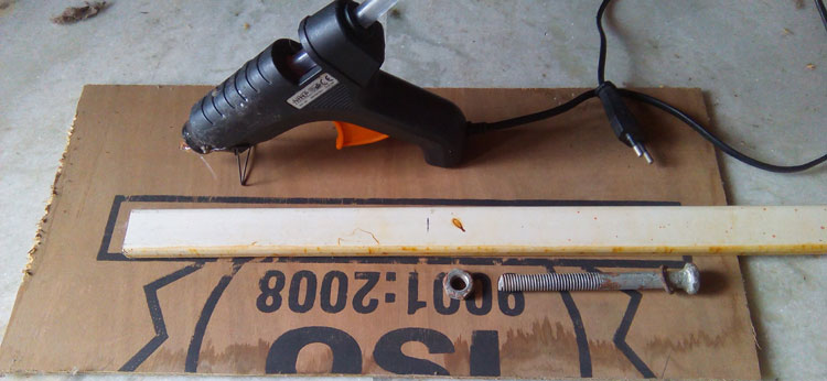
Building the Ultrasonic Levitation Setup
Please note that for this project, correctly mounting ultrasonic transducers is important. They should face each other in the opposite direction which is very important and they should be in the same line so that ultrasonic sound waves can travel and intersect each other in opposite directions. For this, you can take two small pieces of wood or MD board, nut bolt, and glue. You may make two holes to fit the transducer perfectly by the drill machine. On the stand, you can hang the ultrasonic transducer arrangement.
In this case, I used two pieces of cardboard and then fixed ultrasonic Transducer with the help of glue from the glue gun. Later, for making the stand, I used a simple wiring casing box and fixed everything with glue.
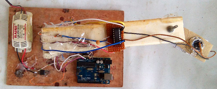
Here are some pictures of ultrasonic levitation that show the working of the project.
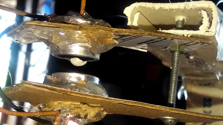
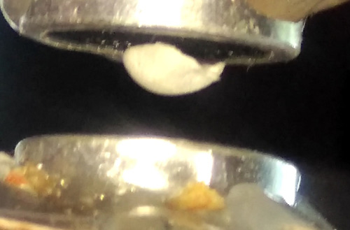
The ultrasonic levitation or acoustic levitation also works if one side is mounted with the ultrasonic transducer but a reflector will be needed in that case which will act as an obstacle so that it can be used in hoverboard in future and anti-gravity transportation. You can also check out the complete working video below.
I hope you understood the project and enjoyed building something fun. If you have any questions, please leave them in the comment section below, you can also use our forums for other technical questions.
byte TP = 0b10101010; //every 2nd port receives the opposite signal
void setup()
{
 DDRC = 0b11111111; //Define all analog ports as outputs
  // Initialize timer 1
  noInterrupts();           // Disable interrupts
  TCCR1A = 0;
  TCCR1B = 0;
  TCNT1  = 0;
  OCR1A = 200;              // Set Compare Match Register (16MHz / 200 = 80kHz square -> 40kHz full wave)
  TCCR1B |= (1 << WGM12);   // CTC mode
  TCCR1B |= (1 << CS10);
  TIMSK1 |= (1 << OCIE1A);  // Switch on Compare Timer Interrupt
  interrupts();             // Activate interrupts
}
ISR(TIMER1_COMPA_vect)
{
  PORTC = TP; // Send the value TP to the outputs
  TP = ~TP;   // Invert TP for the next run
}
void loop(){
  // there is nothing left to do here:-(
}