

Raspberry Pi and Arduino are the two most popular open source boards in Electronics Community. They are not only popular among Electronics Engineers but also among school students and hobbyists, because of their Easiness and Simplicity. Even some people just started liking Electronics because of Raspberry Pi and Arduino. These boards have great powers, and one can build very complicated and Hi-fi project in few simple steps and little programming.
We have created number of Arduino Projects and Tutorials, from very simple ones to complicated ones. We have also created Series of Raspberry Pi Tutorials, from where anyone can start learning from 'scratch'. This is a small contribution towards Electronics Community from our side and this portal has proved itself as Great Learning Resource for Electronics. So today we are bringing these two great boards together by Interfacing Arduino with Raspberry Pi.
In this tutorial, we will establish a Serial Communication between Raspberry Pi and Arduino Uno. PI has only 26 GPIO pins and zero ADC channels, so when we do projects like 3D printer, PI cannot do all the interactions alone. So we need more output pins and additional functions, for adding more functions to PI, we establish a communication between PI and UNO. With that we can use all the function of UNO as they were PI functions.
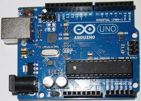
Arduino is a big platform for project development, having many boards like Arduino Uno, Arduino Pro mini, Arduino Due etc. They are ATMEGA controller based boards designed for Electronic Engineers and Hobbyists. Although there are many boards on Arduino platform, but Arduino Uno got many appreciations, for its ease of doing projects. Arduino based program development environment is an easy way to write the program when compared to others.
Components Required:
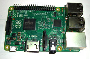
Here we are using Raspberry Pi 2 Model B with Raspbian Jessie OS and Arduino Uno. All the basic Hardware and Software requirements, regarding Raspberry Pi, are previously discussed, you can look it up in the Raspberry Pi Introduction, other than that we need:
- Connecting pins
- 220Ω or 1KΩresistor (2 pieces)
- LED
- Button
Circuit Explanation:

As shown in the Circuit Diagram above, we will connect UNO to the PI USB port using USB cable. There are four USB ports for PI; you can connect it to any one of them. A button is connected to initialize the serial communication and LED (blink) to indicate that data is being sent.
Working and Programming Explanation:
Arduino Uno Part:
First let’s program the UNO,
Connect the UNO to the PC first and then write the program (Check Code section below) in the Arduino IDE software and upload the program to the UNO. Then disconnect the UNO from PC. Attach the UNO to the PI after programming and connect an LED and button to the UNO, as shown in circuit diagram.
Now the program here initializes the Serial Communication of UNO. When we press the button attached to the UNO, the UNO sends few characters to the PI serially through USB port. The LED attached to the PI blinks to indicate the characters being sent.
Raspberry Pi Part:
After that we have to write a program for PI (Check Code section below), to receive this data being sent by UNO. For that we need to understand a few commands stated below.
We are going to import serial file from library, this function enables us to send or receive data serially or by USB port.
import serial
Now, we need to state the device port and the bit rate for the PI to receive the data from UNO without any errors. The below command states that, we are enabling the serial communication of 9600 bits per second on ACM0 port.
ser = serial.Serial('/dev/ttyACM0', 9600)
To find out the port which the UNO being attached to, go to the terminal of PI and enter
ls /dev/tty*
You will have the list of all attached devices on PI. Now connect the Arduino Uno to Raspberry Pi with USB cable and enter the command again. You can easily identify the UNO attached port from the displayed list.
Below command is used as forever loop, with this command the statements inside this loop will be executed continuously.
While 1:
After receiving the data serially we will be displaying the characters on the screen of PI.
print (ser.readline())
So after the button, attached to the UNO, is pressed we will see characters being printed on the PI screen. Hence we have established a Basic Communication Handshake between Raspberry Pi and Arduino.
Complete Project Code
// Code for Arduino Uno
void setup()
{
pinMode(2,INPUT);                            // PIN2 is set for input
pinMode(3,OUTPUT);                        // PIN3 is set for output
Serial.begin(9600);                             // serial data rate is set for 9600bps(bits per second)
}
void loop()                                           // execute the loop forever
{
  if(digitalRead(2)==LOW)                 // if button attached to the UNO is pressed
    {
     digitalWrite(3,HIGH);                         // turn ON the LED at PIN3
     Serial.println( "ButtonPressed" );        // send "ButtonPressed" string of characters serially out
     delay(200);                                           // wait for 200 milli second
     digitalWrite(3,LOW);                          // turn OFF the LED
    }
}

# Code for Raspberry PI
import time
import serial
ser = serial.Serial('/dev/ttyACM0', 9600)         # enable the serial port
while 1:                                                             # execute the loop forever
ser.readline()                                                     # read the serial data sent by the UNO
print (ser.readline())                                          # print the serial data sent by UNO

Can we program arduino from raspberry pi ? With the same IDE