

Arduino Due is an ARM controller based board designed for electronic engineers and hobbyists. ARM architecture is very influential in modern electronics, we use them everywhere like our mobiles, iPods and computers etc. If someone wants to design industrial systems it must on ARM controllers. ARM controllers are very important because of their agility.
We have already covered the basics of Arduino Due in Getting Started with Arduino Due. Now in this tutorial we are going to adjust the brightness of an LED, by using PWM signal generated by DUE. A DUE PWM (Pulse Width Modulation) signal provides a variable voltage over constant power supply.
Pulse Width Modulation:
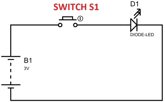
In above figure, if the switch is closed continuously over a period of time, the LED will be ‘ON’ during this time continuously. If the switch is closed for half second and opened for next half second, then LED will be ON only in the first half second. Now the proportion for which the LED is ON over the total time is called the Duty Cycle, and can be calculated as follows:
Duty Cycle =Turn ON time/ (Turn ON time + Turn OFF time)
Duty Cycle = (0.5/ (0.5+0.5)) = 50%
So the average output voltage will be 50% of the battery voltage.
This is the case for one second and we can see the LED being OFF for half second and LED being ON the other half second. If Frequency of ON and OFF times increased from ‘1 per second’ to ’50 per second’. The human eye cannot capture this frequency of ON and OFF. For a normal eye the LED will be seen, as glowing with half of the brightness. So with further reduction of ON time the LED appears much lighter.
We will program the DUE for getting a PWM and connect a LED to show its working.
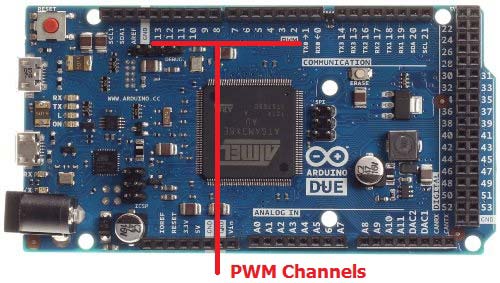
There are 12 PWM Channels (Pin 2 to Pin 13) in the DUE and we can use any one or all of them. In this case we will stick to one PWM signal at PIN2.
Components:
- Arduino Due
- Power supply (5v)
- LED
- Buttons (two pieces),
- 1KΩ resistor (two pieces), 220Ω resistor
And Arduino IDE - Arduino Nightly Software (https://www.arduino.cc/en/Main/Software).
Circuit Diagram and Working Explanation:

The circuit is connected on breadboard as per the Circuit Diagram. However one must pay attention during connecting the LED terminals. Although the buttons can show bouncing effect but in this case it does not cause considerable errors, so we need not worry this time.
Getting a PWM signal from DUE is easy; Arduino IDE provides useful features which eases the programmer’s difficulty. If we go for bare chip programming, we need setting up an ATMEGA controller for PWM signal, which is not easy; we have to define many registers and settings for an accurate signal, however in Arduino we don’t have to deal with all those things. We have already covered Pulse width Modulation with ATmega32 ,with Arduino Uno and with 555 timer IC.
By default all the header files and registers are predefined by Arduino IDE, we simply need to call them and that’s it, we will have a PWM output at appropriate pin. We also need to call certain commands to get a PWM signal, these are discussed below:
pinMode(2, OUTPUT)
analogWrite(pin, value)
First we need to choose the PWM output channel or select a pin from 12 pins of DUE, after that we need to set that pin as output. Since we are using PIN2 as output, we will set it as OUTPUT as shown in first line.
Next we need to enable the PWM feature of DUE by calling the function “analogWrite(pin, value)”. In here ‘pin’ represent the pin number where we need PWM output. We are putting it as ‘2’, so at PIN2 we are getting PWM output. “Value” is the turn ON value, it varies between 0 (always off) and 255 (always on). We can write the appropriate value in this space for required brightness of LED.
We attached a couple of button to the DUE board for varying this value. One button is for incrementing the brightness value and other is for decreasing the brightness value. Once the Due is done programming, we can adjust brightness by pressing these buttons.
Complete Project Code
volatile int brightness = 0;         //initializing a integer for incrementing and decrementing duty ratio.
void setup()
{
  // declare pin 2 to be an output:
  pinMode(2, OUTPUT);
  pinMode(14, INPUT);
  pinMode(15, INPUT);
}
// the loop routine runs over and over again forever:
void loop()
{
  if(digitalRead(14)==HIGH)
  {
    if(brightness<255)
    {
      brightness++;        //if pin14 is pressed and the duty ratio value is less than 255, increase the ‘brightness’
    }
    delay(20);
  }
    if(digitalRead(15)==HIGH)
  {
    if(brightness>0)
    {
      brightness--;        //if pin15 is pressed and the duty ratio value is greater than 0, decrement the ‘brightness’
    }
    delay(20);
  }
  analogWrite(2, brightness);
}
