
The Bluetooth Amplifier Module is useful for DIY projects for creative and hobbyists. The module’s Bluetooth connectivity makes the project connect wirelessly and gives hustle-free entertainment. The board can work on Lithium-ion/Li-Po or Lead Acid battery, which is used to make the device portable. Its design makes it easy to implement the module for projects that are handy, cheap, and provide High Sound Quality.
You can build your own DIY Bluetooth Music Player using Audio Amplifier to use at home/office, or while traveling.
In this project, we will learn the connections and circuitry of the Module. Also, gather some necessary information and Technical Specifications.
Circuit Digest have built many audio circuits, check out the huge collection of audio circuits with schematics and detailed explanation, to help you build Audio projects and use them for your Audio designs. Also check previously built DIY music player:
- MP3 Player Circuit
- Simple Arduino Audio Player and Amplifier with LM386
- DIY ESP32 Based Audio Player
- Subwoofer Amplifier Circuit using IC TDA2030
Wireless Hi-Fi Bluetooth Amplifier Module
Wireless HI-FI module is a Class AB / Class D switching function, 5.3W output power single channel audio power amplifier Board with Built-in Bluetooth, FM, USB, aux cable, and memory chip decoder support.
With its comprehensive set of input ports and impressive features such as compactness, attractive design, and high audio quality, this module stands out from other boards. Its versatility makes it a preferred choice for various applications.
- A power switch to turn ON/Off the module.
- A micro-USB charging connector at fixed 5-volt input.
- AUX-Cable 2.5 mm female Input Jack.
- USB card, TF card Input ports.
- Inbuilt Bluetooth & FM Support.
- A Multi-Purpose Functioning Switch.
- It has two inbuilt Red & Green LED indicators [see their functionality later].
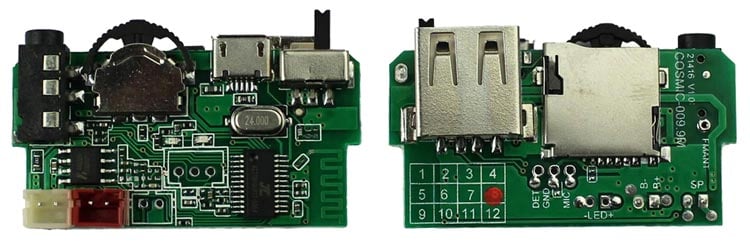
The module has a lot more internal options for supporting other features. The module also has two Open connections to connect MIC and an extra LED for power indication, as indicated in the below diagram.
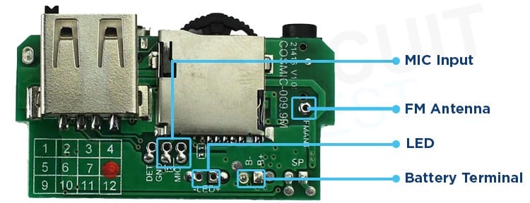
- Connecting an extra LED to the Board will not be effective as it only indicates the ON/OFF status according to the power switch.
- Soldering a small piece of wire to the FM Antenna Terminal will make the signals and audio quality better while in FM Mode.
- Connecting MIC is very helpful & Futuristic for your project. It allows you to talk on calls during the module connected to the smartphone via Bluetooth or AUX.
Bluetooth Audio Amplifier Circuit Diagram

Let’s have a look at the comprehensive circuit connections of the Board which are very straightforward & simplest design to understand.
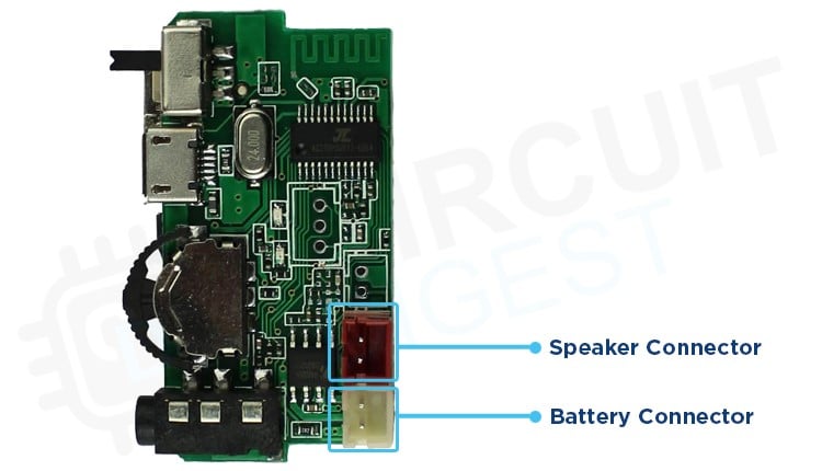
Connect the Battery to the battery connector of the module. You can use a 3.7-volt lithium-ion Battery or a 4-volt Lead Acid Battery.
Battery Input-voltage Range: Using this Module, we can able to see the battery draining percentage in our Smartphone. This function purely works based on the Remaining battery voltage which is sensed by the controller IC.
- At 3 volts, it shows the battery fully drained [0%] while at 4.2-volts it sensed the battery as fully charged [100%].
- We can give up to 5 volts to the battery terminals of the module to boost the audio quality performance of the audio IC.
Note: This module can also work with the direct power of a Micro-USB charging Connector whose input is fixed at 5 volts without any battery.
Speaker Matching Specifications
The Module uses a HAA2018 audio IC whose Vdd range is 2.5-5.5 volts. It is a Class AB / Class D switching function, 5.3W output power single channel audio power amplifier IC whose Technical Specification are:
Class D output power:
- 5.3W (VDD=5.0V, RL =2Ω,THD+N=10%)
- 3.2W (VDD=5.0V, RL =4Ω,THD+N=10%)
Class AB output power:
- 5.2W (VDD=5.0V, RL =2Ω,THD+N=10%)
- 3.1W (VDD=5.0V, RL =4Ω,THD+N=10%)
The RL denotes the Load Impedance whereas the VDD is the battery terminal voltage to the audio IC.
Others Features:
- Low distortion and low noise
- Start-up POP sound suppression function
- Shutdown current is less than 1uA
- Overheat protection function
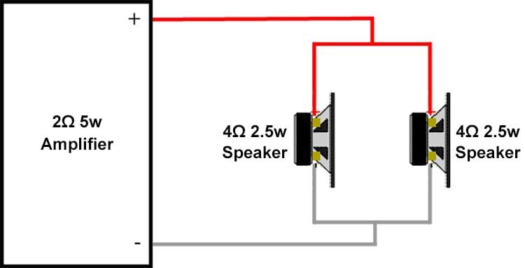
Since, from the above technical specification, you can be aware that at 2Ω Load impedance, the output power will be highest. If you can find 2Ω 5w Speaker, then it will be well & good otherwise you have to set a Series/parallel combination of speakers to match the impedance and power rating according to the output rating of the Amplifier module. In general, it is advisable to match both the impedance and power ratings when connecting speakers and amplifiers. If possible, it is recommended to use a speaker with an impedance that matches the amplifier's output impedance. Additionally, selecting a speaker with a power rating equal to or higher than the amplifier's output power will provide better performance and reduce the risk of damaging the components.
Since our Amplifier output rating is 2Ω 5w, hence I am using two 4Ω 2.5w speakers in parallel connection which is equivalent to the Amplifier output.
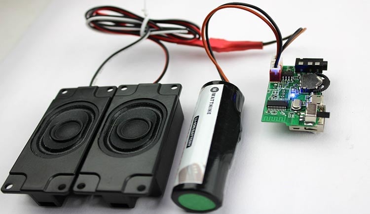
Let’s have a look at the real circuit prototype in the below image
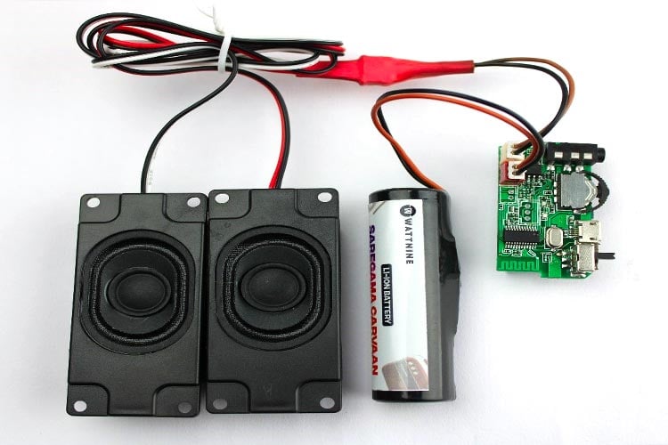
Demonstration of Bluetooth Audio Amplifier Board
We have already seen the connection details above, and now we get an insight into the functioning of such a kind of Board like how its indicators work differently in different modes.
- Connect the lithium-ion battery properly by taking care of +ve & -ve correct terminals. Also, connect the speakers with the correct matching for proper audio quality.
- Turn-On the switch and check for a Blue blinking LED.
Mode and LED Indicator
The Module works in different Five types of Modes, these are Bluetooth, FM, AUX, Pendrive, and SD-card Mode. The Blue LED indicator indicates a bit differently in each mode, making it easy to understand the internal functioning of the board.
Bluetooth Mode: The module is always in BT mode by default after turning ON the Board.
- The Blue Led blinks fastly until the BT will not be paired.
- Led Continuous ON after pairing or while pausing the song.
- Blinks Slowly while playing the Song.
FM Mode: Holding & pressing the multi-function button towards the center will change the mode to FM.
- The Blue Led blinks fastly until all the channels will not be scanned.
- Blinks Slowly while playing a channel.
USB/SD-card Mode: The module will automatically initiate the USB-drive mode when you plugged in a USB-Drive.
- Led Continuous ON while pausing the song or if there is no song inside the memory drive.
- Blinks Slowly while playing the Song.
Note: Mp3 songs must be present in the Flash drive otherwise it won’t Access the USB drive.
AUX Mode: Connect an AUX cable to provide audio input to the board from Smartphone.
- Always Blinks Slowly while playing/pausing the Song.
Charging Functionality
It has a Micro-USB input port to charge the Battery pack attached to the Module. There is a Red Led to indicate the charging mode of the module. The Red Led is continuously glowing while battery charging.
Charging voltage at battery terminal: 4 volts
Charging current: ∼200 mA
Note: Don’t charge the device while using it because it will not charge your battery.
Hope you enjoyed the project and learned something useful from it. If you have any questions, you can leave them in the comment section below.

Can you please describe which Wireless Hi-Fi Bluetooth Amplifier Module you used for this very interesting article? Thank you.
Mike