

Digital Code Locks are very popular in Electronics, where you need to enter a particular ‘Code’ to open the Lock. This type of Locks needs a Microcontroller to compare the entered code with the predefined code to open the Lock. We have already built these kinds of Digital Locks using Arduino, using Raspberry Pi and using 8051 microcontroller. But today here we are building the Code Lock without any Microcontroller.
In this simple circuit we are building 555 Timer IC based Code Lock. In this Lock, there will be 8 buttons and one needs to press specific four buttons simultaneously to unlock the Lock. The 555 IC is configured as a Monostable Vibrator here. Basically in this circuit we will have an LED at the output pin 3 which turns ON when trigger is applied by pressing those specific four buttons. LED remains On for some time and then turns Off automatically. The On time can be calculated with this 555 monostable calculator. LED represents the Electric Lock here which remains locked when there is no current and gets unlock when current passes through it. The combination of specific four buttons is the “Code”, which needs to open the Lock.
Required Components:
- +5V Supply Voltage
- 555 Timer IC
- 470Ω resistor
- 100Ω resistor (2 pieces)
- 10KΩ resistor
- 47KΩ resistor
- 100µF capacitor
- LED
- Push Button (8 pieces)
Circuit Explanation:
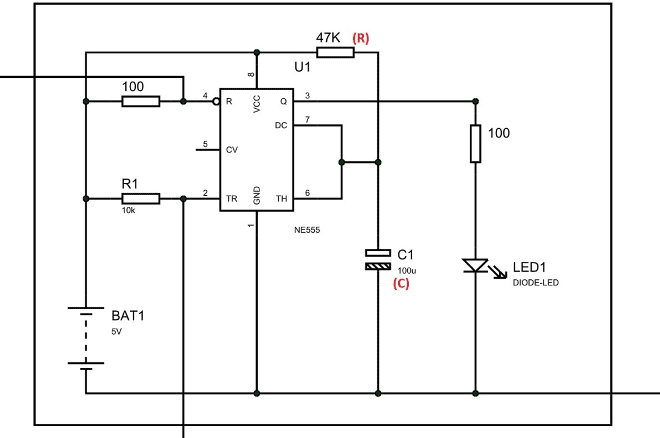
The figure shows the circuit diagram of 555 based Code Lock,

As shown in the circuit we have a capacitor between PIN6 and GROUND this capacitor value determines the turn on time of LED once a trigger is passed. This capacitor can be replaced with higher value for more Turn On time duration for a single trigger. With decreasing the capacitance we can decrease the Turn On time after a trigger. The supply voltage applied in the circuit can be any voltage from +3V to +12V and it must not exceed 12V doing so will result in chip damage. Rest of the connections are shown in the Circuit Diagram.
Working Explanation:
As mentioned earlier, here 555 IC is configured in Monostable Multivibratior mode. So once the trigger is given by pressing the Push Button, LED will turn ON and output will stay HIGH until capacitor connected at PIN6 charges to the peak value. The time for which the OUTPUT will be high can be calculated by the below formula.
T = 1.1*R*C
So according to values in our circuit, T = 1.1*47000*0.0001 = 5.17 seconds.
So the LED will be ON for 5seconds.
We can Increase or Decrease this time by changing the capacitor value. Now why this time is important? This time duration is the time for which the Lock will remain open after entering the correct code or pressing the correct keys. So we need to provide sufficient time for user to get enter through the door after pressing correct keys.
Now, we know that In 555 timer IC, no matter what the TRIGGER is, if the RESET pin is pulled down the output will be LOW. So here we will use the Trigger and Reset pins to build our Code Lock.
As shown in circuit, we have used Push Buttons in the jumbled way to confuse the unauthorized access. As in circuit, the TOP layer buttons are “Linkers”, they all need to be pressed together for the TIGGER to be applied. The BOTTOM layer buttons are all RESET or “Mines”; if you press even one of them the OUTPUT will be LOW even if LINKERS are pressed simultaneously.
Note here that Pin 4 is the Reset Pin and Pin 2 is the trigger Pin in 555 timer IC. Grounding Pin 4 will reset the 555 IC and grounding Pin 2 will trigger the output to be high. So to get the Output or to open the Code Lock, one must press all the buttons in the TOP layer (linkers) simultaneously without pressing any button in Bottom layer (Mines). With 8 buttons we will have 40K combinations and unless the correct LINKERS are known, it will take forever to get the correct combination to open the Lock.
Now, lets discuss the internal working of the circuit. Let’s assume that the circuit is connected on the bread board as per the circuit diagram and given power. Now the LED will be OFF as the TRIGGER is not given. The TRIGGER PIN in the timer chip is very sensitive and it determines the output of 555. A low logic on TRIGGER pin 2 SETS the flip-flop inside the 555 TIMER and we get High Output and when trigger pin is given High logic the output remains LOW.
When all the keys in Top Layer (Linkers) are pressed together, then only trigger pin gets Grounded and we get Output as HIGH and lock gets unlocked. However this high stage can’t be retained for long once the trigger is removed. Once the LINKERS are released, the HIGH stage of output merely depends on the charging time of the capacitor connected between Pin 6 and ground as we discussed earlier. So the Lock will remain unlocked until the capacitor gets charged. The capacitor once reaches a voltage level it discharges through the THRESHOLD pin (PIN6) of 555, which pulls down the OUTPUT and LED turns off as capacitor discharges. This is how the 555 IC works in Monostable Mode.
So this is how this Electronic Lock works, you can further replace the LED with actual Electric Door Lock using a Relay or Transistor. This kind of real Electric Door Lock is presented here in this project: Arduino Door Lock
Comments
Yeah you can strip off a mobile wire and take of red and black wires which will be positive and negative respectively. You'll get5v
How can we change code of this system?
u can divide this layout into 2 part and the first on crk and 2 one switch and the connect both with jumper wire and and after that on changing series wire u can change the code
How to connect the lock? And what kind of lock will be used? I want to try this one. Thanks!
You can use Electric Door Lock to be triggered with this circuit, check this article for how Electric Door lock works: Arduino RFID Door Lock
u can connect the code lock by using relay
where LED glow take as input for the relay
Please someone send me PCB layout of this circuit
Without using microcontroller,What additions should be done to the above ckt so that the user has three chances of entering the correct code?
why use 10k resistor for pin 2(trigger).
The LED is not staying LED after removing the fingers from the button.
Should I use a ceramic capacitor?

Can we use mobile charger that supply 3V or 3.7V.
Please answer