

When you are searching for a Microcontroller there is a lot of variety available in the market from various reputed manufacturers like Microchip, ST Microelectronic, Texas Instruments, and the list goes on and on. But when we try to differentiate those microcontrollers with form factor vs features vs price, it gets very hard to choose one. However, Megawin, a Taiwan-based manufacturing company that was established in 2011 came up with a 20 PIN low cost 8051 based microcontroller named MG82F6D17.
The Megawin MG82F6D17 is an 8051 based 20-pin microcontroller out of which 18 are I/O pins. It comes with features like UARTs, I2C, 6-Ch PWM, SPI, DMA, PLL wake up functions, Brownout detectors Timer Counters, and more. It also has 16KB of user programming space or flash memory and a total of 1K of RAM which in comparison makes it more powerful than an ATmega8 Microcontroller. Now you should be wondering what the price is? It's less than 0.67$ (50 INR) only. Additionally, it doesn't require an oscillator, since it’s equipped with 12 MHz internal RC oscillators.
In this tutorial, we will learn all about the MG82F6D17 Microcontroller and we will also learn how to program the MG82F6D17 microcontroller. Since it is a very cheaper one and has a wide range of features, you can find this microcontroller interesting if you are a beginner, or you are doing production stuff with this microcontroller. Throughout this tutorial, we will learn how to set up the MG82F6D17 programming environment as well as how to write the first hello world program of the embedded world - blinking an LED.
Selecting Hardware and Software Development Tools for MG82F6D17 Microcontroller
Since the MG82F6D17 microcontroller is developed above an 8051 Core, it's time to find out the proper hardware and software that is required for programming the microcontroller. Let's start with the hardware requirement as it's the easiest one.
Hardware Requirements
In this section of this article, we will talk all about the hardware requirements for this project.
MG82F6D17 Development Hardware
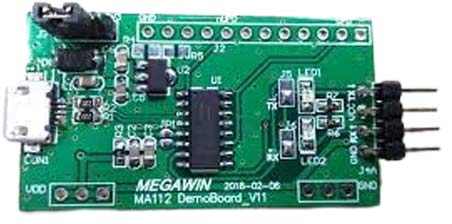
The official development board for Megawin is the MA112 Development Board which requires an ISP programmer and debugger to program it easily. If you don't want to get your hands dirty and just want to get up and running you might want to prefer buying this one.
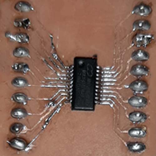
But as we thought to go way cheaper, we will buy IC and make a small breakout board that we will use to test and program the IC. A breakout board become necessary because the pin pitch of the IC is very small, but if you are using the DIP version of the IC this is not necessary,
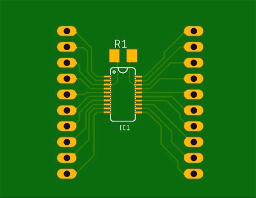
Shown above is PCB. The board is just a simple development board with all pinouts from the microcontroller unit. In the above image, the internal circuit diagram for the development board is shown.
Megawin ISP Programmer
To program this microcontroller, it’s recommended to use the Megawin ISP programmer that is the recommended tool by Megawin but as the main focus of this article is to chop off the development and testing cost, we will be using a USB to UART FTDI module to program this IC.
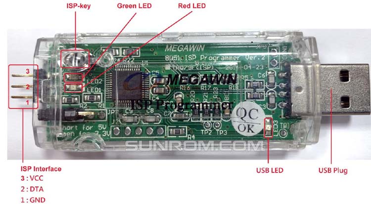
Yes, you read that right as the datasheet of the MG82F6D17 suggests it can be easily programmed by a simple FTDI USB to UART module.
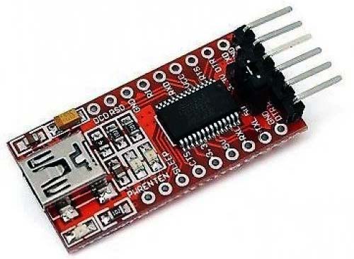
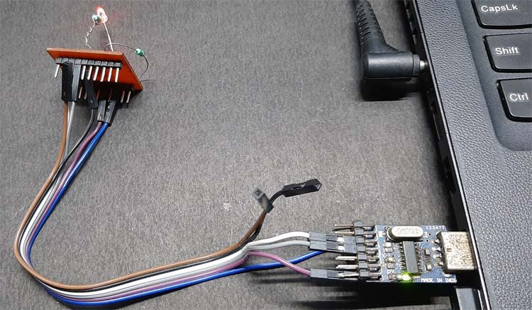
An image of the FTDI module is shown above we will be using this USB to UART module to program this device.
Software Requirements
In this section of this article, we will talk all about the software requirements for this project.
IDE and Compiler for Megawin MG82F6D17 Microcontroller
A proper IDE and compiler become very important for any microcontroller programming. For the industry-leading microcontroller manufacturers, such as a microchip, Nordic, STMicroelectronics - they all provide free c compiler and IDE. But when we are talking about Megawin controllers the support is just not there, this is the one thing that lags. Since it is an 8051 based microcontroller, it can be programmed using Keil u vision with the C51 compiler. But there is a catch. Both tools are great to do the job, but they are not free. There are trial and evaluation versions of these tools available and satisfy the job of programming Megawin MG82F6D17 microcontroller.
We have chosen Keil Micro Vision since the UI is easy to understand, good to configure and the workspace is really useful. Also, there is some official example code that is written on Keil Micro Vision software. It also comes with the C51 compiler that will compile the code for 8051 architecture. And for flashing the microcontroller we will be using the Megawin 8051 COM Port ISP tool provided by Megawin. We will talk about it in the section below when we will go more in-depth about it. When you install Keil for the first time it provides all the necessary libraries required to get up and running with the Megawin series of microcontrollers but for newer devices, we have to install a library and database which we can find on their official website.
Downloading Required Software’s
Now, it is time to download the required software and IDE to create the environment and make it ready for programming. Here is the list of important software that is required to be downloaded before installing anything. Just provide the required information on the Keil-C51 download page.
- Keil Micro Vision - C51 (IDE with Compiler)
- FTDI Drivers
- New Device Database: Megawin 8051 OCD ICE for KEIL
- Megawin 8051 COM Port ISP
- MG82F6D17 Beta Driver
That’s all to download and install to get up and running if you already have an FTDI or similar USB to UART converter you can absolutely skip the second step.
Install the Keil u Vision
After downloading the Keil micro vision, install it in the default directory. It will look something similar to the image shown below.
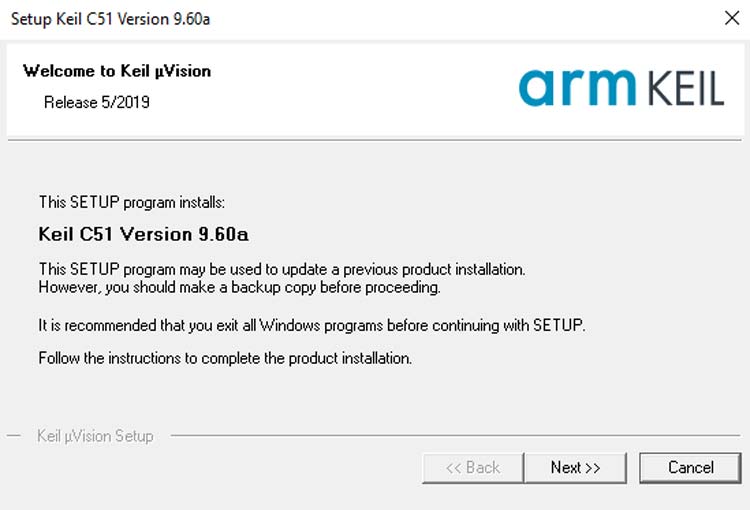
You click next and then you leave it to its default location and click next.
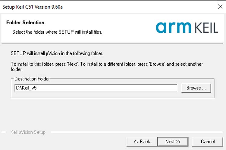
Once you click next it will be installed in the default location. Next, we have to install the database for the Megawin microcontroller.
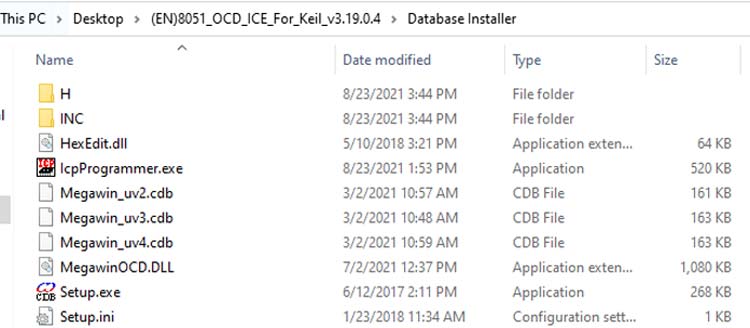
Install Additional database for Keil
In order to work with newer devices within Keil, you need to install an additional database, you can go to the download link given above and download the file as shown below and you click and install it with the setup.exe file.
Once you double click on the setup file you will be prompted to provide the installation location for the Keil IDE. For me it was on the default C: drive and as you can see when you click on the install button you will be prompted with a Database is installed successfully! message.
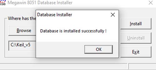
Now you are all done with setting up the environment and the IDE.
Installing the Program Upload Tool
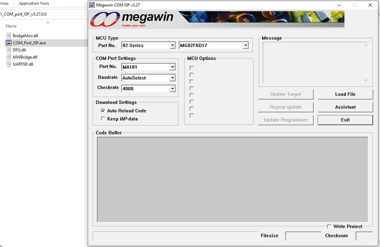
Installing the program upload tool is very simple you just need to download the COM Port ISP tool (link given above), and double click to run it and it will open up the tool ready to flash the chip, Image is shown below;
Now we are all done with software and hardware requirements. And we can move on to the actual coding part. But before that let’s look at the hardware with a few details.
Designing the test PCB
As you have probably seen in the cover photo we have designed a custom PCB for the project. In this section of the article, we will talk about all that, let’s start with the PCB. It was designed with EAGLE PCB Design Software. The schematic is shown below, it's a pretty small breakout board with a 100K pulldown resistor that is recommended as per the datasheet of MG82F6D17 IC.
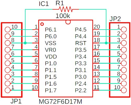
Once the basis schematic of the breakout board is done, the final design of the PCB looked like the image below.
You can download the required files to make this PCB from the link below. And in terms of components, there's not much, you need a piece of clad board, the main microcontroller ic, and a 100K resistor will do the trick.
- Download the Schematic PDF or Image File
- Download the Gerber Files for the PCB
- Download the PCB Layout in PDF or Image File
Circuit Diagram for Blink an LED on MG82F6D17 using Keil
Once the PCB was done, I soldered an LED with a 1K Resistor according to the schematic given below.

Blink an LED on MG82F6D17 using Keil
If you go through the normal process and set up a new project this will take a lot of time and you will have to get through a lot of setting to get your project up and running. That is why I prefer to download the example code from the Megawin website and start my work from there this makes the job so much easier. You can download the files from the MG82F6D17 Beta Driver that you can find on the Megawin website. Once you downloaded and extracted the file you will get two folders one is named Sample and another one is named Example_Project. We will open up the sample folder and open it with the Keil micro vision, the process is shown below.
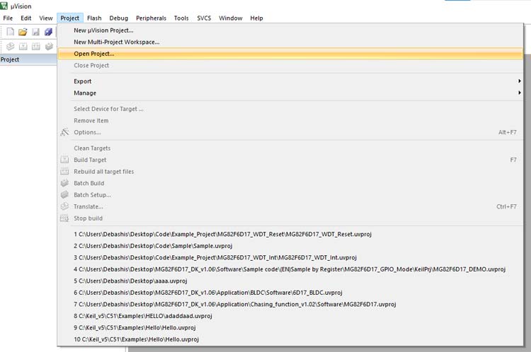
Go to Project and click on Open Project… locate your download location and open up the sample project and it will look something like the image below
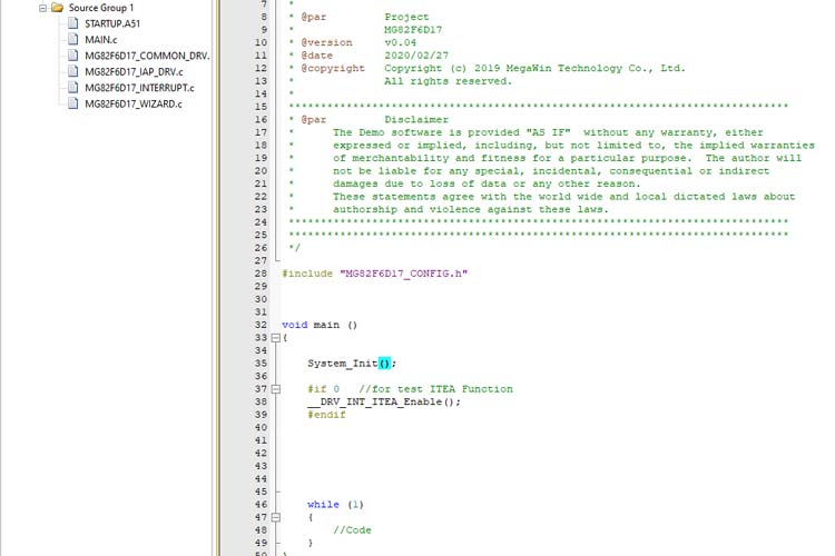
Now you are up and running without breaking a sweat, but don’t forget to make a copy of the sample project for future use. Now just open the main.c file and write this code. We will only be testing the board and environment for now. We will get into the details of the code later. For the complete code, click here
#include "MG82F6D17_CONFIG.h" // Add in the config header otherwise the code will not compile
#define MCU_SYSCLK            12000000  //we define the internal clock frequency
#define MCU_CPUCLK            (MCU_SYSCLK) // this stateent is internally excuted inside the library and sets the clock to 12MHz
#define LED_PIN         P34 // We define the P3.4 pin as Led Pin (We have connected an LED on this pin)
/**
 an workaround for delay in the system as its provided by megawin themself
 this statement takes in one 8-bit unsifgend number and depending upon the clock frequency
 executes a certain number of NOP's to make an jely bean delay
Function:         void DelayXms(u16 xMs)
Description:    dealy£¬unit:ms
Input:                  u16 xMs -> *1ms  (1~65535)
Output:
**/
void DelayXus(u8 xUs) //
{
      while(xUs!=0)
      {
#if (MCU_CPUCLK>=11059200)
            _nop_();
#endif
#if (MCU_CPUCLK>=14745600)
            _nop_();
            _nop_();
            _nop_();
            _nop_();
#endif
#if (MCU_CPUCLK>=16000000)
            _nop_();
#endif

#if (MCU_CPUCLK>=22118400)
            _nop_();
            _nop_();
            _nop_();
            _nop_();
            _nop_();
            _nop_();
#endif
#if (MCU_CPUCLK>=24000000)
            _nop_();
            _nop_();
#endif
#if (MCU_CPUCLK>=29491200)
            _nop_();
            _nop_();
            _nop_();
            _nop_();
            _nop_();
            _nop_();
#endif
#if (MCU_CPUCLK>=32000000)
            _nop_();
            _nop_();
#endif

            xUs--;
      }
}
/*************************************************
this DelayXms call the previous DelayXus a certin number of time in order to virtully
make that amout of dely.
Function:         void DelayXms(u16 xMs)
Description:    dealy£¬unit:ms
Input:                  u16 xMs -> *1ms  (1~65535)
Output:
*************************************************/
void DelayXms(u16 xMs)
{
      while(xMs!=0)
      {
            DelayXus(200);//  when this function is called the first function in the DelayXus gets executed.
            DelayXus(200);
            DelayXus(200);
            DelayXus(200);
            DelayXus(200);
            xMs--; // run this loop until this function reaches zero
      }
}
void main ()
{
    System_Init(); // Initilize the sysem that is required by internal process
    while(1)
    {
                  LED_PIN = 0; // make the LEDpin low
                  DelayXms(1000); // Delay for 1S and
                  LED_PIN = 1; // Make the Led pin High
                  DelayXms(1000); // Delay for 1S
            }
}
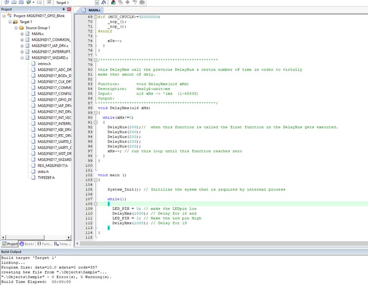
Now compile this code and it will not provide any error or warnings. The output will be-
compiling MAIN.c...
linking...
Program Size: data=10.0 xdata=0 code=359
creating hex file from ".\Objects\Sample"...
".\Objects\Sample" - 0 Error(s), 0 Warning(s).
Build Time Elapsed:  00:00:00
MG82F6D17 LED Blink Code Explanation
The code is ready to flash. Before flashing, it is important to know what is happening inside the code. The LED is connected in between pin no 16 which is pin 3.4 and ground. Therefore, the LED will glow when this pin goes high.
while(1) {
             LED_PIN = 0; // make the LEDpin low
             DelayXms(1000); // Delay for 1S and
             LED_PIN = 1; // Make the Led pin High
             DelayXms(1000); // Delay for 1S
}
The main logic for blinking an LED stays the same. Another function is defined in the above code section. The above function is a software-based delay using nops in the loop. However, it doesn’t provide accurate timing. But right now, this is what is recommended by Megawin. The best way to create accurate timing is to use the timer of the microcontroller unit, which we will learn in another tutorial.
Uploading Code on MG82F6D17 using a USB to UART Converter
Now, let’s flash the code into the hardware. For that connect the hardware to the PC. Make sure that the power led of the USB to UART converter is glowing perfectly as shown below.
Next, we open up the code in Keil IDE and compile it, a reference image is shown below
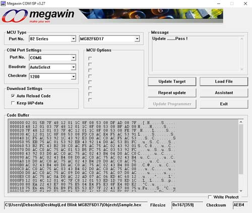
Once that is successful, we need to open up the Megawin Comp Port ISP software. In that, we first set the device then set the COM port to load the Hex file that you will be able to find in the sample folder inside your project file and click on the update target button.
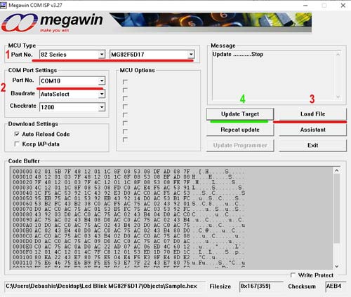
Now you are ready to upload the code to your board, but there is a little trick to upload the code. When step 3 from the above image is done, disconnect power from the board. If it’s connected then you have to click on the Update Target button. Once you click on that you will see the update prompt then you have to connect the power to the board, only then you will be prompted with a Pass! message as shown in the image below.
See the video linked below to understand the process of flashing the code in the chip. Well, this is all for the tutorial. We have learned the basics of hardware, have set up the development environment and learned how to compile and upload code. We are now ready to progress and we will be using this in all our upcoming tutorials. If you have any questions, please post them on our forums and stay tuned for more!!
