
VU Meter or Volume Meter is very popular and fun project in Electronics. We can consider the Volume Meter as an Equalizer, which is present in the Music systems. In which we can see the dancing of LEDs according to the music, if music is loud then equalizer go to its peak and more LEDs will glow, and if music is low then lesser number of LEDs shall glow. Volume Meter (VU) is an indicator or representation of the intensity of sound level over LEDs and can also serve as a volume measurement device.
Previously we built the VU Meter without using Microcontroller and audio input was taken from Condenser Mic. This time we are building VU Meter using Arduino and taking the audio input from 3.5 mm jack, so that you easily provide audio input from your Mobile or Laptop using AUX cable or 3.5 mm audio jack. You can easily build it on Breadboard but here we are designing it on PCB as a Arduino Shield using EasyEDA online PCB simulator and designer.
Components Required:
- Arduino UNO
- VU Meter Arduino Shield (Self Designed)
- Power Supply
Components for VU Meter Arduino shield:
- 3.5mm Audio Jack
- SMD type Resistors 100 ohm (10)
- LEDs
- Burg strips
Designing Volume Meter (VU) Shield for Arduino:
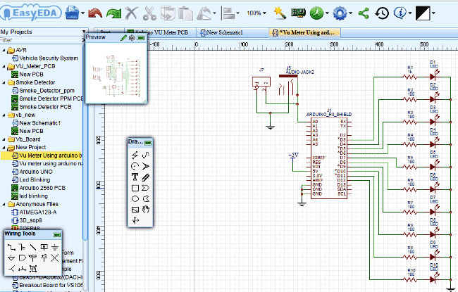
For designing VU Meter Shield for Arduino, we have used EasyEDA, in which first we have designed a Schematic and then converted that into the PCB layout by Auto Routing feature of EasyEDA.
EasyEDA is a free online tool and one stop solution for developing your electronics projects with ease. You can draw circuits, simulate them and get their PCB layout in just one click. It also offers Customized PCB service, where you can order the designed PCB in very low cost. Check here the complete tutorial on How to use Easy EDA for making Schematics, PCB layouts, simulating the Circuits etc.
EasyEDA has recently launched its new version (3.10.x), in which they have introduced many new features and improved the overall user experience, which makes EasyEDA more easier and usable for designing circuits. New version includes: improved MAC experience, improved components search dialog, update PCB layout in one click, add design notes in a frame below schematic and many more, you can find all the new features of EasyEDA version 3.10 here. Further they are soon going to launch its Desktop version, which can be downloaded and installed on your computer for offline use.
We have made the Circuit and PCB design of this VU Meter Shield public, so you can just follow the link to access the Circuit Diagram and PCB layouts.
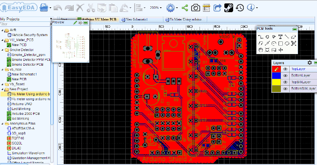
Below is the Snapshot of Top layer of PCB layout from EasyEDA, you can view any Layer (Top, Bottom, Topsilk, bottomsilk etc) of the PCB by selecting the layer form the ‘Layers’ Window.
If you find any problem in using EasyEDA, then check out our previously created 100 watt inverter circuit, where we have explained the process step by step.
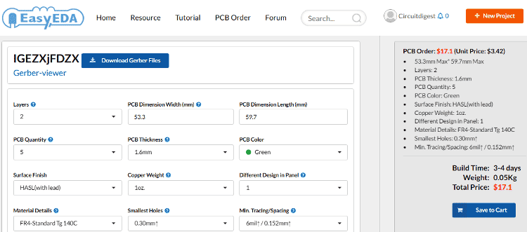
Ordering the PCB online:
After completing the design of PCB, you can click the icon of Fabrication output, which will take you on the PCB order page. Here you can view your PCB in Gerber Viewer or download Gerber files of your PCB and send them to any manufacturer, it’s also a lot easier (and cheaper) to order it directly in EasyEDA. Here you can select the number of PCBs you want to order, how many copper layers you need, the PCB thickness, copper weight, and even the PCB color. After you have selected all of the options, click “Save to Cart” and complete you order, then you will get your PCBs a few days later.
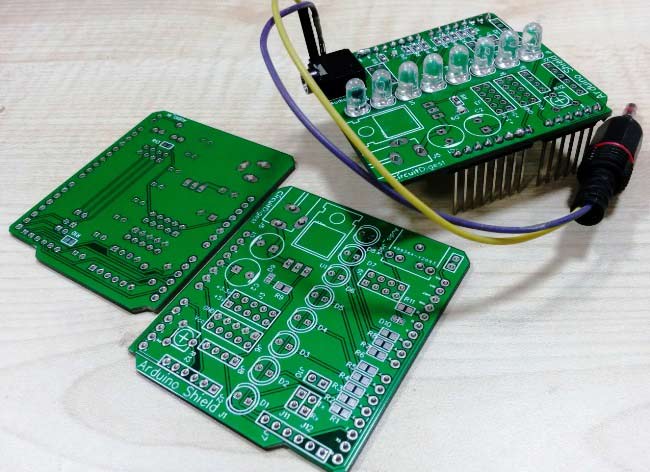
After few days of ordering the PCB, we got our VU Meter Arduino Shield PCB, and we found the PCBs in nice packaging and the quality of PCB is quite impressive.
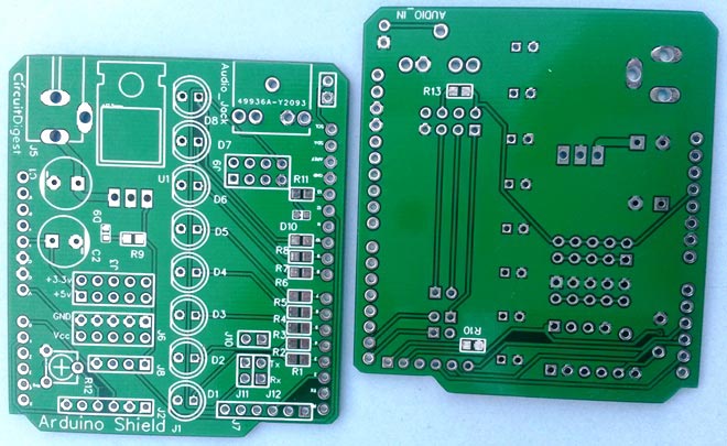
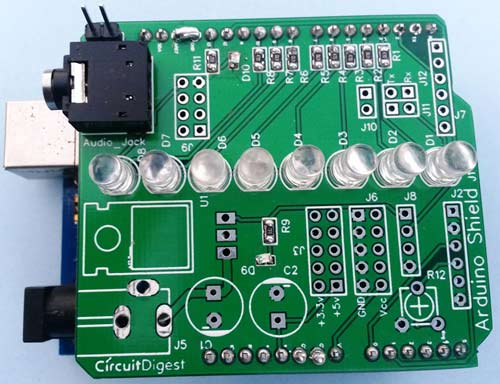
After getting the PCBs, we have mounted and soldered all the required components and burg strips over the PCB, you can have a final look here:
Now we just need to place this VU Meter Shield over the Arduino. Align the Pins of this Shield with the Arduino and firmly press it over the Arduino. Now just upload the code to the Arduino and power on circuit and you are done! Your VU Meter is ready to dance on music. Check the Video at the end for demonstration.
Circuit Explanation:
In this VU Meter Arduino Shield, we have used 8 LEDs, in which 2 LEDs are of Red color for Higher Audio Signal, 2 Yellow LEDs are for mediate audio signal and 4 Green LEDs are for Lower audio Signal. We can add some more option in this Shield by connecting LCD, ESP8266 Wi-Fi module, DHT11 H&T Module, voltage regulator, more VCC, +5v, +3.3v and GND pins. But here in demonstration of this project we have assembled only LEDs, audio jack and power LED. Here in this shield, we have used some SMD components that are resistors and LEDs. Also we have two options to apply audio signal to this board that are direct to pins or by using audio jack.
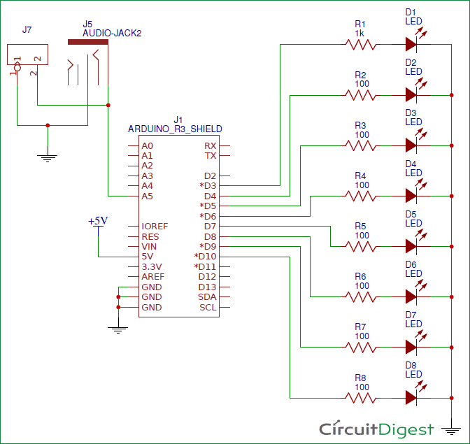
Circuit for this project is very simple, we have a connected 8 LEDs at pin numbers D3-D10. Audio Jack is directly connected at analog pin A5 of Arduino.
If you need to connect LCD then you can connect the LCD at J1 and J7 (see below circuit) with connections like lcd(14, 15,16,17,18,2).

Programming Explanation:
Program of this Arduino VU Meter is very easy. Here in this code we haven’t given any name to particular LED. I just keep in mind the connection and write code directly.
In the given void setup() function we initialize the output pins for LEDs. Here we can see a for loop in which we initialize the value of i=3 and run it to 10. Here i=3 is the third pin of Arduino and whole for loop will initialize the pin D3-D10 of Arduino.
void setup()
{
  for(i=3;i<11;i++)
  pinMode(i, OUTPUT);
}
Now in void loop() function we read the analog value from the A5 pin of Arduino and store that value in a variable namely ‘value’. Now this ‘value’ is divided by 10 to get a result and this result is directly used to get pin no of Arduino using for loop.
void loop()
{
  int value=analogRead(A5);
  value/=10;
  for(i=3;i<=value;i++)
  digitalWrite(i, HIGH);
  for(i=value+1;i<=10;i++)
  digitalWrite(i, LOW);
}
It can be explained by example, like suppose the analog value is 50, now divide it by 10, we will get:
Value = 50
Value = value/10
Value = 50/10 = 5
Now we have used for loop like:
  for(i=3;i<=value;i++)
  digitalWrite(i, HIGH);
In above ‘for’ loop i=3 is D3 and Value=5 means D5.
So it means loop will go from D3 to D5 and LEDs that are connected at D3, D4 and D5 will be ‘ON’
And in below ‘for’ loop i=value+1 means value=5+1 means D6 and i<=10 means D10.
  for(i=value+1;i<=10;i++)
  digitalWrite(i, LOW);
Means loop will go from D6 to D10 and LEDs that are connected at D6-D10 will be ‘OFF’.
So that’s how we can build our own VU Meter Arduino Shield, in which LEDs will glow according to the intensity of the sound like you can check in Video below. You can directly provide input from your mobile or laptop by using 3.5 mm audio jack or AUX cable and have fun with the beautiful lighting effect.
Complete Project Code
int i=0;
int value1=0;
void setup()
{
  for(i=3;i<11;i++)
  pinMode(i, OUTPUT);
}
void loop()
{
  int value=analogRead(A5);
  value/=10;
  for(i=3;i<=value;i++)
  digitalWrite(i, HIGH);
  for(i=value+1;i<=10;i++)
  digitalWrite(i, LOW);
}
