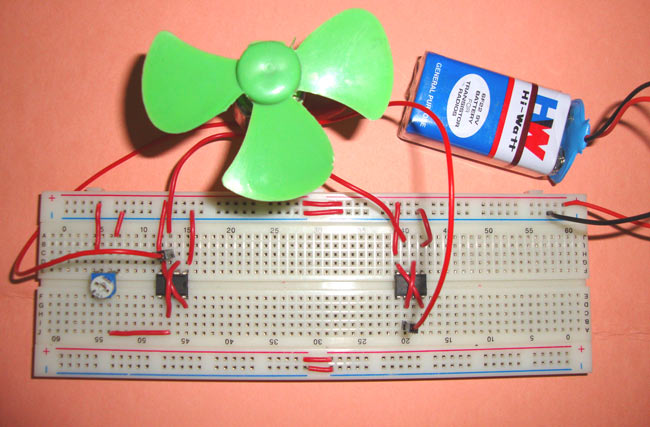
H-bridge is the circuit in which voltage can be applied across the load, in either of the direction. These circuits are frequently used in robotics, especially for the DC motor. Voltage can be applied in either direction to rotate the DC motor forward or backward. DC motor further move the robot or any robotic system, forward or backward.

This H-bridge can be created using 555 timers. 555 timer IC is a great component in electronics, it can be used as current source and can also be used as a current Sink. 555 timer can also drive current upto 200mA, which is sufficient to drive a small DC motor.
This H-Bridge Circuit is very simple and can be created using few components:
- Two 555 timer ICs
- A Potentiometer (10k to 100k)
- DC motor
- Battery
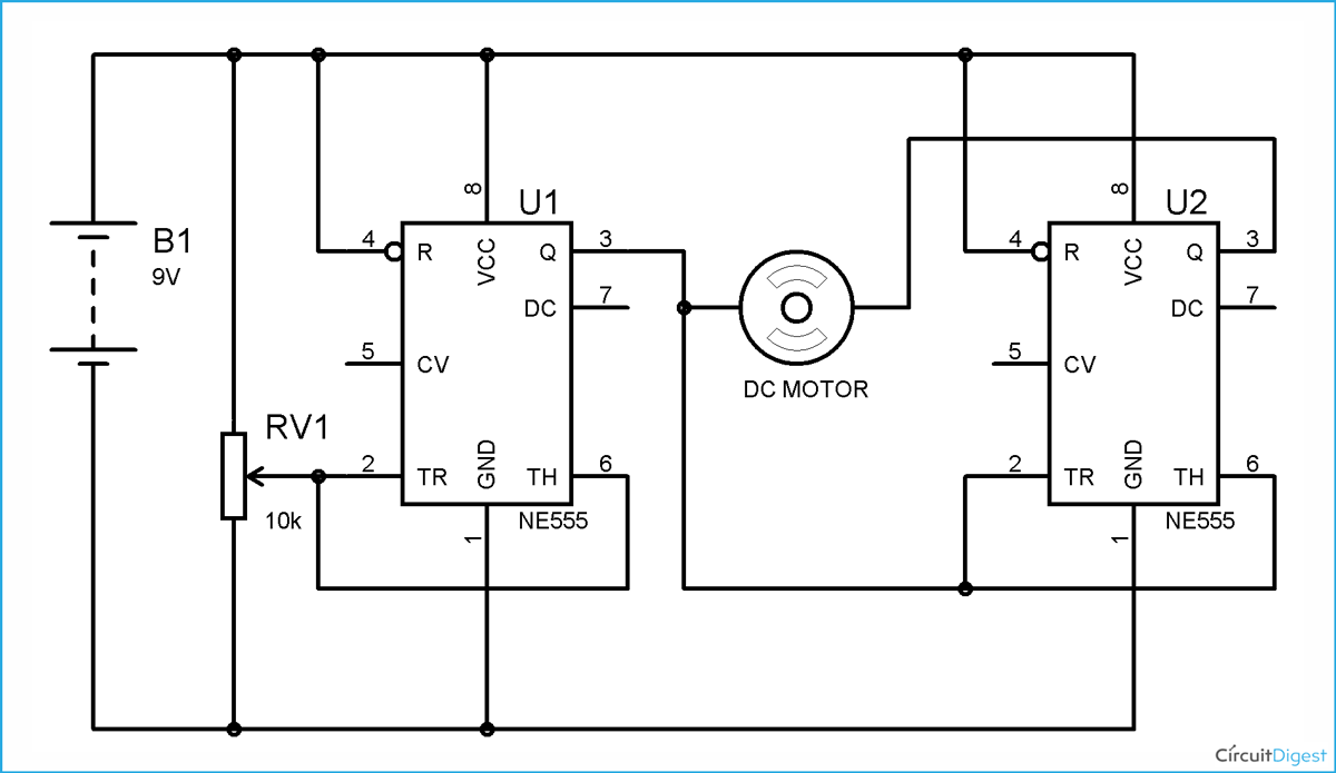
Connect the circuit according to the below schematic diagram for H-bridge motor driver. When we move the 10k pot in one direction, the DC motor rotates in one direction and when we move the Pot to opposite direction then the motor also rotate in opposite direction.
When we move the Pot in one direction the voltage at Trigger PIN 2 goes below the Vcc/3 , which is the inverting input of Lower comparator inside 555 ic. This sets the OUTPUT of the flip-flop and 555 behaves as the current source and the other 555 behaves as the current sink. And DC motor starts rotating in one direction.
When we move the Pot in opposite direction, the voltage at Threshold PIN 6 goes above the 2/3Vcc, which is the non-inverting input of Upper comparator inside the 555 IC. This resets the output of the Flip-flop and 555 behaves as the Current sink and at the same time other 555 acts as Current source, which rotate the DC motor in opposite direction.
Remember, to rotate the DC motor you need to use proper power supply, either use a new or fully charged 9v battery or use your computer USB 5v supply.
[Also check this Circuit DC Motor Speed Control]
Comments
can i replace motor with led,nd what is rpm of dc motor


I think an astable "multivibrator will work to run a timer for a small water pump running on 12VDC My wife has a hydroponics experiment going and is trying to run it on solar power. The only timers we've been able to find are 120 VAC and that requires an inverter and it runs the battery down even though we have nominal 90 watts of solar cells. I'm guessing we get maybe 45 watts an hour and I want to lower the total power draw by running straight 12VDC with no inverter. How much drive current can this circuit provide?:
Thanks
Chris