

Fuse is a vital protection device for many electronic devices. They simply monitor the current consumed by the circuit/load and in the event of unsafe current flowing through the circuit the fuse will blow itself and thus prevent the load/circuit form getting damaged by that high current. This type of fuse is called a mechanical fuse and there are many types of fuse such as fast blow, slow blow etc, but they suffer from one common draw back. When a fuse is blown it has to be replaced by the consumer/operator to make the device function normal again. This is the reason why many old electronic devices like toaster or electric kettle had a spare fuse provided along with the product.
To overcome this drawback, most of the modern electronic devices use an Electronic Fuse. An Electronic Fuse serves the same purpose of that of a mechanical fuse but it requires no replacement. It has a power electronic switch inside with closes and opens the circuit as required. In the unlikely event of a failure the switch is open the circuit and isolate it from the power supply, once the favorable condition returns the fuse can be reset by just clicking on a button. There is no hassle of purchasing a suitable value of fuse and replacing it for the old one. Interesting right?!! So, In this tutorial we will learn how to construct an Electronic Fuse circuit, how it works and how you could use one in your designs.
Electronic Fuse Circuit Diagram:
The complete circuit diagram for an electronic fuse circuit is shown below. As shown in the circuit, it involves only few circuits and hence it is easy to construct and implement into our designs.

Here the circuit is constructed to monitor the operating current of a motor (LOAD), which operates on 12V. You can replace the load with any circuit whose current you are trying to monitor. The resistor R1 determines how much current can be allowed through the circuit before the circuit reacts for an over-current scenario. We will discuss the functionality of each component and how to choose the values based on your requirement.
Working:
The working of the electronic fuse circuit can be easily understood by taking a look at how the SCR works. Under normal condition the user has to press the button to connect the load to the power supply. When the button is pressed the Gate pin of the SCR is connected to source voltage through a 1K Resistor. This will trigger the SCR and thus makes it to close the connection between the Cathode and the Anode pin. Once the connection is closed, current starts to flow from the Source (+12V) to the load through the Anode to Cathode pin of the SCR.
When the button is released, the SCR will remain turned ON because there is no commutation circuit to turn it off. Thus the SCR gets latched in ON state and stays there until the current flowing though it goes below the holding current of the SCR.
What is meant by Commutation in Thyristors (SCR)?
A Thyristor once turned ON by a signal will not turn OFF by itself when the signal is removed. So to turn OFF a Thyristor we need some external circuit and this circuit is called as commutation circuit. The process of turning ON a Thyristor by providing a Gate pulse is called as triggering and the process of turning OFF a Thyristor is called as Commutation.
What is holding current in a Thyristor (SCR)?
The holding current (do not confuse this with latching current) is the minimum value of current that should flow through the Anode and Cathode pin of a Thyristor to keep it turned ON. If the value of current reaches below this value then the Thyristor turns OFF by itself without any external commutation.
The SCR used in our circuit is TYN612 which has a maximum holding current of 30mA (refer datasheet to know the value), so if the current flowing though the Anode and Cathode gets less than 30mA the SCR will turn itself OFF. Thus isolating the power form the load.
The resistor R1 (0.2 ohms) and the transistor (2N2222A) plays a vital role in turning off the SCR. Under normal condition when the load(motor) is operating, it draws current through the resistor R1. According to Ohms law the voltage drop across the resistor can be calculated by
Voltage across the resistor = Current through circuit x Resistor value
So according to the formulae the voltage drop across the resistor is directly proportional to the current flowing through the circuits. As the current increase the voltage drop across the resistor will also increase, when this voltage drop exceeds the value of 0.7V. The transistor gets turned ON, because the resistor is connected directly across the Base and Emitter pin of the transistor. When the transistor closes the complete current required for the circuit flows through the transistor momentarily during which the SCR is turned OFF since the current through it has gone below holding current and the voltage drop across the resistor also gets 0V since no current is flowing through it. Finally the Transistor and the SCR is turned off and the Load (Motor) is also isolated from the power supply. The complete working is also illustrated using the GIF image below.
An Ammeter is placed through the resistor to monitor the current flowing through the Anode Cathode terminal of the SCR. This current should not go below the holding current of the SCR (the holding current for the SCR in simulation is 5mA), if it goes below this value the SCR will turn OFF. Also a voltmeter is placed across the resistor 150 ohms to monitor the voltage across it and check if the NPN transistor is being triggered before the SCR closes.
Hardware:
As told earlier this circuit has a minimum number of components, it involves one SCR, one transistor and a couple o resistors. Hence it can be easily analysed by building it on a breadboard. Again, it depends on your application. If you are planning anything that is more than 2A, then breadboard is not recommended. I build the electronic fuse circuit on a bread board and it looked something like this below.

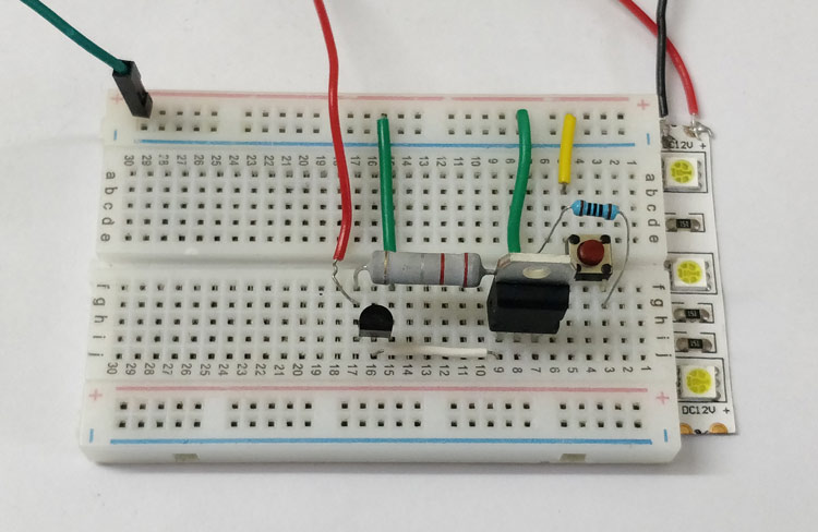
As you can see in the image I have used an LED strip as my load, you can use a different load or even connected your circuit which has to be protected. To connect the load to the power supply we have to press the button which will turn on the SCR. Also note that I have used a 2W 0.2 Ohm resistor as my R2 since we have to allow a large value of current it is always important to consider the wattage rating of this resistor.
Since I was not able to create a fault condition by increasing the current rating I reduced the voltage to create a fault and thus reduce the current through the SCR. Alternatively you can also short the Collector Emitter pin of the transistor with a wire this make the current flow through the wire and not through the SCR and thus the SCR will turn off. After the fault is made and recovered, the circuit can again be turned ON by simply pressing the button as earlier. The complete working of the circuit is also shown in the video below. Hope you understood the circuit and enjoyed learning it. If you have any doubt please feel free to post them on the comment section below or use the forums for technical help.
Limitations:
Like all circuit this also has certain limitations with it. If you think that these will affect your design then you should find an alternative
- The entire load current flows through the resistor R2, hence there is a power loss across it. Hence this circuit is not suited doe battery operated applications
- The current rating for which the fuse is designed for will not be accurate since each resistor will vary bit and as it gets aged the property of the resistor will also change.
- This circuit will not react for sudden spike currents since the transistor requires some time to react to the changes.
Comments
is BT151 can be used in this
is BT151 can be used in this circuit?

is good!