

Voltage fluctuations have always been a problem and are responsible for most of the failure in AC appliances. Be it a normal home appliance like a Toaster or a high performance industrial machine like a CNC, everything has a rated voltage only on which it will run without any problem at its maximum efficiency. Unfortunately our Domestic/Industrial Lines fails to provide us that rated voltage due to various reasons, hence in this project we are going to build a simple electronic circuit breaker which could trigger a relay to disconnect the load when a high/low voltage detected.
This project is designed around the famous op-amp LM358. We are going to make the op-amp work in Differential mode thus making it to compare the current voltage with a preset voltage. The whole project can be built on a bread board (except the power lines) and could be made to work in no time. So let us get started.....
Components Required for Circuit Breaker:
- LM358 (Dual Package Op-amp)
- 7805 (+5V regulator)
- 12V Step Down Transformer
- 5V Relay
- BC547 (2Nos)
- 10K Variable POT
- 1K,2K,2.2K,10K,5.1K Resistors
- 100uF, 10uF, 0.1uF Capacitors
- Diode Bridge
- Connecting Wires
- Bread Board
Circuit Diagram:
The complete schematic diagram of electronic circuit breaker is given in the image below. Read further for the explanation of the same.

Circuit Explanation:
As shown above in circuit breaker schematic, it is really simple and just a bunch of resistors, capacitors and other stuff. But what actually happens behind all these. How the values of the components are selected and what is the role of them here?
I have tried to answer this question by breaking them into each segments and explaining them below.
Power Section:
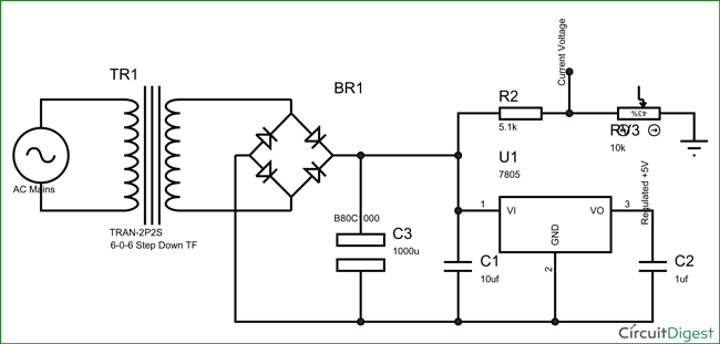
The op-amp is the heart of this electronic circuit breaker diagram. We need a regulated 5V supply to power this op-amp. Also we need to feed the current voltage (Voltage at any particular time) to the op-amp. The op-amp can handle only up to 5V since it is powered by 5V. Hence we need to convert the Input AC voltage (220V AC) to 0-5V DC.
So the above circuit solves two purposes.
- Provide a constant 5V for powering up the circuitry
- Maps down the Input AC voltage to 0-5V for the op-amp
To achieve this we have used a 12V Step Down transformer which converts the 220V AC to 12V AC then we rectify it with a diode bridge to 12V DC (Approx) and then regulate voltage to 5V by using a 7805 Voltage regulator. Any changes in the input voltage will affect the value of voltage in the output side of the diode bridge. Hence this voltage can be considered as the “current voltage” of the AC mains. By using a 5.1K resistor and a 10K POT (forming a potential divider) we have mapped the voltage between 0-5V.
Op-Amp Section:
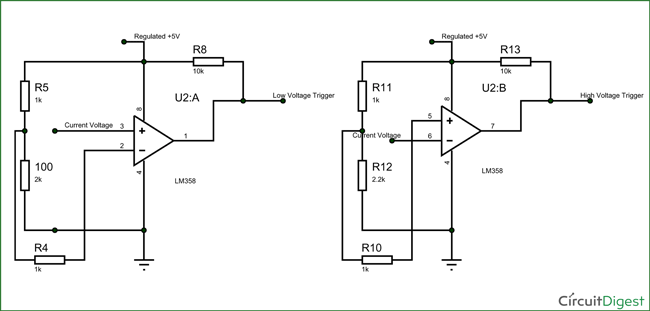
This section is the part where the comparison takes places. We have two subdivisions in the op-amp section. One is used to compare the “current voltage” with High Voltage value and the other is used to compare with Low voltage Value. Both the sections are shown in the image below.
The op-amp circuit shown above is the Differential mode of an Op-amp. Op-amp are really a work horse for most of the electronics circuits, it has many mode of operation and applications like Summing, subtracting, amplifying etc... We have used it as a voltage a comparator here.
So what is a voltage comparator and why do we need them here?
A voltage comparator in our case compares the voltage between the pins 3 and 2 and if the voltage on pin 3 is greater than pin 2 then the output at pin 1 gets high (3.6V) else the output will be 0V. We compare the “current Voltage” with the preset High and Low voltage to get a high/low voltage trigger.
In the circuit shown above the low voltage threshold is set on pin 2 using the resistors 1K and 2K. The high voltage threshold is set on the pins 5 using the 1K and 2.2K resistors.
Using these resistors forms a potential divider and provides a 3.33V of low voltage cut off and 3.43V as high Voltage cut-off. This means that only if the “current voltage” is between 3.33V to 3.43V both the op-amps will go high.
Note: I have set the threshold voltages at 3.33V and 3.43 Volt since my upper cut off was 230V and lover cut-off was 220V. You can set them accordingly and then calibrate the circuit by using the 10K pot to control the “current voltage”.
Relay Section:
This is the place where we attach the AC load. The relay is use to turn ON/OFF the AC load.
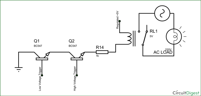
As discussed in the op-amp section. Both the op-amp will get high only if the voltage is in-between the High and Low voltage cut-off limits. So we have to turn ON an AC load only if both the op-amp’s outputs are high. Here the “Low Voltage Trigger” and “High Voltage Trigger” are the output of the pin 1 and pin 7 respectively.
Only if both are high, the Relay will get its ground and the will be triggered. The AC load (here a Lamp) id connected through the relay. A resistor of 1K is used for current limiting.
Once you understand how the circuit works making it work will be not a problem. Simply wire up the circuits and use the 10K pot to set our “current Voltage” between your “High Voltage Trigger” and “Low Voltage Trigger”. Now if there is any change in the AC main Voltage either of your op-amp will go low and your relay will turn off, thus turning off the Load connected to it.
You can also use the simulation file attached here, to verify/modify your circuit based on your High or low voltage threshold values.
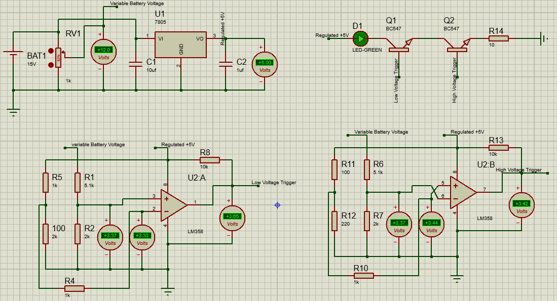
The simulation uses a Potentiometer to vary the input voltage and a Green LED as a load. You can also monitor the voltage values at each terminal which will help you to understand the circuit much better.
Hope you liked this circuit breaker project and understood the working behind it. The complete working of the project can be seen in the video below.
This project suffers from the following drawbacks which you might want to consider just in case if it means to you.
- The voltage measured here is not Vrms voltage. The value is also subjected to peaks and ripples
- Your Load might experience a switching effect if the voltage drops/rises gradually (in most cases it won’t).
- Do not connect loads that consume current more than 5A. This will most likely kill your relay and its driver.
You can also check this similar project to learn more: High/Low Voltage Detection using PIC Microcontroller
Comments
Hi mark Church,
Yes mark you can use the same concept, but connect use the same circuit since your peak current is too much for the relay to Handel.
You should modify the Relay and the Relay driver to match up with your current ratings. Also since the load you are dealing with is big I would also strongly recommend you to add some protection circuit circuit and isolation circuit for better and safety working.
thanks
give me a full modified circuit
What is low and high voltage in circuit
Q1 and Q2 are drawn not correctly
Hi Dima,
I just went through circuit and was not able to find anything wrong with Q1 and Q1.
What makes you thing that they are not correct?
Kindly send me the full schematic of this circuit I want it for my university project!
From where i can get the pcb for this circuit?
Great page! Do you know the make and model of that transformer???
Transistor q1 is not working when it is connected to negative terminal plz help me.

Grate project, I have a project i will be starting soon involving a remotely controlled boar pump and this would be ideal for switching the pump. I would like to know if it would handle 12.5 AMP at start up.
Thanks mark.