At many places, like public speeches or some musical program, where loudspeaker is used, we hear music and voice from the same speaker. You might have noticed that as soon as someone starts speaking into the microphone, the music from the loudspeaker stops and we start to listen the voice of the speaker. And vice versa when person stops speaking, the music starts again. In such case, the music or tone gets completely off when the microphone is on. It is called as a Voice-over circuit.
In a voice-over circuit, the voice has a higher priority level than signal. If the voice is present or the microphone is on, the other signal gets off immediately to provide the microphone audio to the speaker. So, in a voice-over circuit, there are two inputs, one has a higher priority than the other one. The higher priority input is connected with the microphone. It is different from the voice modulator circuit, where the input audio is distorted to produce modulated audio.
In this project, we will build an Audio voice-over circuit where two inputs will be available. We will use a push button to activate the voice over feature, that means when the switch is pressed, the voice over will happen and the higher priority Input will be available at the output speaker.
We will do the following things in Audio Voice Over Circuit-
- We will connect a Speaker across the amplifier.
- The circuit will have two inputs.
- In general, the circuit will take audio input from any 3.5mm audio jack like iPod, Mobile phones, Music player system etc.
- In the other input, a microphone will be connected for voice over.
- We will add a Tactile switch to activate the voice-over.
- When the switch is pressed the microphone will get the first priority and the microphone will get connected with the output speaker via the amplifier.
In the case of second input which is at the higher priority level, we will connect an Electret microphone or capsule microphone. We will drive a speaker, with 8 Ohms impedance and .5 Watt RMS output, using the LM386 based audio amplifier circuit. LM386 is an exceptionally good small power amplifier which is capable to drive 8 Ohms .5 Watt speaker.
Required Components
- LM386
- 10uF / 16V capacitor
- 470uF / 16V
- 0.047uF / 16V Polystar Flim Capacitor
- 10R ¼ Watt
- 12V Power Supply unit
- 12V Relay
- Tactile switch
- 3.5mm Audio Jack
- 8 Ohms / .5 Watt Speaker
- Capsule or Electret Microphone
- .1uF capacitor
- 10k 1/4th Watt Resistor
- Bread Board
- Hook up wires
If you are interested in Vero board the following things will be additionally needed-
- Soldering Iron
- Soldering Wire
- Vero board.
Circuit Diagram and Explanation

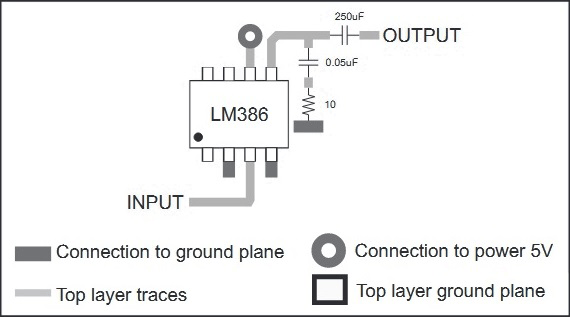
The power amplifier circuit section is taken from the Texas Instrument’s LM386N datasheet.

In the above image, we can see a screenshot from LM386N datasheet from Texas Instruments. The circuit will provide 200x gain on the input signal to the output. The circuit consists few components where two electrolytic capacitors of 10uF and 250 uF (We used 470uF), and one 0.05uF capacitor (0.047 used in our circuit) with a 10 Ohms resistor makes the Power amplifier circuit. Resistors of .047uF and 10 Ohms are creating the snubber circuit across the inductive load (Speaker). The circuit needs to be powered from 5-12V, and load of 4 to 32 Ohms can be connected with the power amplifier.
LM386 Audio Amplifier IC
Pinout and Pin description of LM386 audio amplifier IC is given below
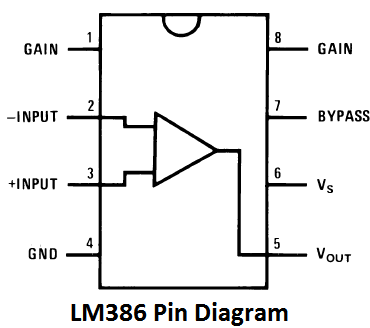
PIN 1 and 8: These are the gain control PINs, internally the gain is set to 20 but it can be increased up to 200 by using a capacitor between PIN 1 and 8. We have used 10uF capacitor C3 to get the highest gain i.e. 200. Gain can be adjusted to any value between 20 to 200 by using proper capacitor.
Pin 2 and 3: These are the input PINs for sound signals. Pin 2 is the negative input terminal, connected to the ground. Pin 3 is the positive input terminal, in which sound signal is fed to be amplified. In our circuit it is connected to the positive terminal of the condenser mic with a 100k potentiometer RV1. Potentiometer acts as volume control knob.
Pin 4 and 6: These are the power supply Pins of IC, Pin 6 for is +Vcc and Pin 4 is Ground. The circuit can be powered with voltage between 5-12v.
Pin 5: This is the output PIN, from which we get the amplified sound signal. It is connected to the speaker though a capacitor C2 to filter DC coupled noise.
Pin 7: This is the bypass terminal. It can be left open or can be grounded using a capacitor for stability
The IC consists of 8 pins, Pin - 1 and pin - 8 are the gain control pin. In the schematic 10uF capacitor is connected across pin 1 to pin 8. These two pin set the output gain of the amplifier. As per the datasheet a design, the 10uF capacitor is connected across these two pins and due to this, the output of the amplifier is fixed to 200x. Learn more about using LM386 audio amplifier IC here.
Microphone (mic)
Next important part is the Electret microphone. An Electrets microphone consists of two power pins, Positive and Ground. We are using Electret microphone from CUI INC. If we see the datasheet we can see the internal connection of the Electret microphone.

An Electret microphone consists of a Capacitor based material which changes the capacitance by the vibration. The capacitance changes the impedance of a Field Effect Transistor or FET. The FET needs to be biased by an external supply source using an external resistor. The RL is the external resistor which is responsible for the gain of the microphone. We used a 10k resistor as RL. We need an additional component, a ceramic capacitor to block the dc and acquiring the AC audio signal. We used .1uF as Microphone DC blocking capacitor.
Relay
The Logical part of the circuit is created by the 12V Relay. We are using a cube relay to change the audio path.
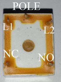
This relay has 5 pins. The L1 and L2 is the internal electromagnetic coil’s pin. We need to control these two pins for turning the relay ‘ON’ or ‘OFF’ and we are doing this thing using the Tactile switch. Next three pins are POLE, NO and NC. The pole is connected with the internal metal plate which changes its connection when the relay gets turned on.
In normal condition, POLE is shorted with NC. NC stands for normally connected. When the relay turned on, the pole changes its position and became connected with the NO. NO stands for Normally Open. So, in normal condition when the relay is in OFF state, if we connect the Audio input signal to the NC pin, the audio will always on until the relay gets energised. And we connected the Mic input through the NO pin. This will set the priority of the microphone or the voice over the music.
Speaker
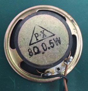
And for the speaker, we used 8 Ohms, .5 Watt speaker. We can see the speaker in the below image-

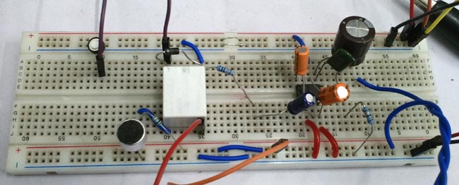
We have constructed the Audio Voice Over circuit on a breadboard-
Testing
To test the circuit, we have played songs from an Android tablet and also used a microphone in voice over mode. Check the complete working of the circuit in the video given at the end-
Improvements
The circuit can be improved by making a proper PCB with proper design reference from the LM386N datasheet. The layout example is given in the below image. Also, the microphone needs to be in close distance from the speaker to reduce feedback related errors. As this circuit work as a one-sided intercom based circuit, we need to add higher wattage amplifier and various tone controls before the microphone and Audio signal input. The circuit can be made stereo by connecting exactly same circuit using two LM386N.