
ATtiny85 Microcontroller Chip is an affordable and powerful alternative to other Arduino microcontrollers, especially when you want to shrink your project down. The chip features 8 pins out of which six are I/O (Including Reset) pins and two are power pins. But how do you program it as it doesn’t have a USB interface like other microcontroller boards? So in this article, I will walk you through the process of programming the ATtiny85 from the Arduino IDE with the help of the Arduino Uno. Basically, we will be using the Arduino UNO as the ATtiny85 programmer.
Components Required for Programming ATtiny85
- Arduino UNO
- ATtiny85 IC
- LED
- 220-ohm resistor
- Breadboard
- Jumper Wires
ATtiny85 Microcontroller Chip - Introduction
Atmel's ATtiny85 is a high performance, low power 8-bit microcontroller based on Advanced RISC Architecture. This microcontroller chip features 8KB ISP flash memory, 512B EEPROM, 512-Byte SRAM, 6 general-purpose I/O lines, 32 general purpose working registers, one 8-bit timer/counter with compare modes, one 8-bit high-speed timer/counter, USI, internal and external Interrupts, 4-channel 10-bit A/D converter, programmable watchdog timer with internal oscillator, three software selectable power saving modes, and debugWIRE for on-chip debugging. ATtiny85 Pinout is given below:
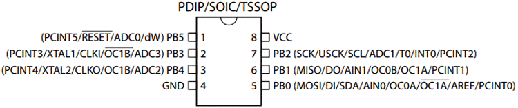
Most of the I/O pins of the chip have more than one function. Check out the table given below to know about the ATtiny85 pin description for each pin.
|
Pin No. |
Pin Name |
Pin Description |
|
1 |
PB5(PCINT5/ADC0/dW) |
PCINT5: Pin Change Interrupt 0, Source5 RESET: Reset Pin ADC0: ADC Input Channel 0 dW: debug WIRE I/O |
|
2 |
PB3(PCINT3/XTAL1/CLKI/ADC3) |
PCINT3: Pin Change Interrupt 0, Source3 XTAL1: Crystal Oscillator Pin1 CLKI: External Clock Input ADC3: ADC Input Channel 3 |
|
3 |
PB4 (PCINT4/XTAL2/CLKO/OC1B/ADC2) |
PCINT4: Pin Change Interrupt 0, Source 4 XTAL2: Crystal Oscillator Pin 2 CLKO: System Clock Output OC1B: Timer/Counter1 Compare Match B Output ADC2: ADC Input Channel 2 |
|
4 |
GND |
Ground Pin |
|
5 |
PB0(MOSI/DI/SDA/AIN0/OC0A/AREF/ PCINT0) |
MOSI: SPI Master Data Output / Slave Data Input DI: USI Data Input (Three Wire Mode) SDA: USI Data Input (Two Wire Mode) AIN0: Analog Comparator, Positive Input OC0A: Timer/Counter0 Compare Match A output AREF: External Analog Reference PCINT0: Pin Change Interrupt 0, Source 0 |
|
6 |
PB1(MISO/D0/AIN1/OC0B/OC1A/ PCINT1) |
MISO: SPI Master Data Input / Slave Data Output DO: USI Data Output (Three Wire Mode) AIN1: Analog Comparator, Negative Input OC0B: Timer/Counter0 Compare Match B Output OC1A: Timer/Counter1 Compare Match A Output PCINT1: Pin Change Interrupt 0, Source 1 |
|
7 |
PB2(SCK/USCK/SCL/ADC1/T0/INT0/ PCINT2) |
SCK: Serial Clock Input USCK: USI Clock (Three Wire Mode) SCL: USI Clock (Two Wire Mode) ADC1: ADC Input Channel 1 T0: Timer/Counter0 Clock Source
INT0: External Interrupt 0 Input PCINT2: Pin Change Interrupt 0, Source 2 |
|
8 |
VCC |
Supply Voltage Pin |
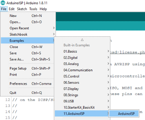
Step 1: Configuring Arduino Uno as an ISP:
Since ATtiny85 is just a microcontroller, it requires an ISP (In-System Programming) to be programmed. So to program the ATtiny85, we need to first configure Arduino Uno as ISP to act as a programmer for the ATtiny85. For that, connect the Arduino Uno to Laptop and open the Arduino IDE. After that, navigate to File > Example > ArduinoISP and upload the Arduino ISP code.
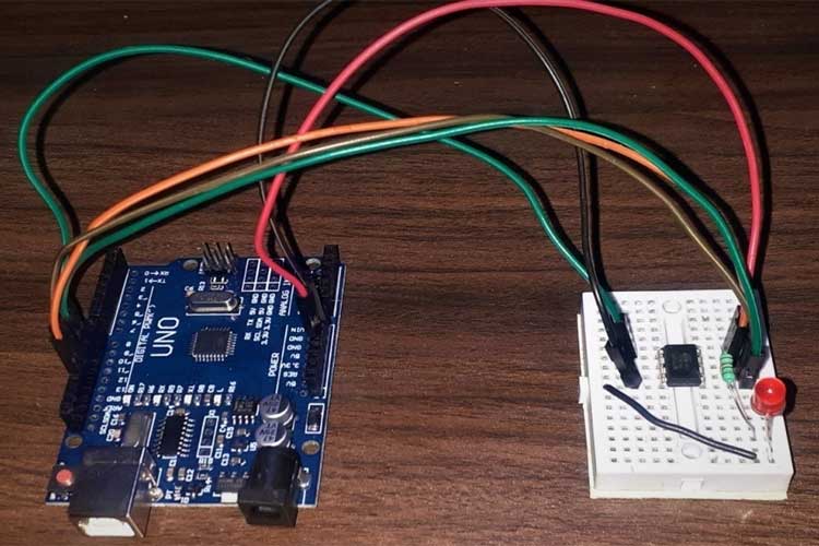
Step 2: Circuit Diagram for Programming ATtiny85:
The complete schematic for Programming ATtiny85 with Arduino Uno is given below:

The positive pin of LED is connected to Pin 0 of the ATtiny85 IC through a 220Ω resistor while the GND pin is connected to the GND of IC. The complete connections are given in the table below:
|
ATtiny85 Pin |
Arduino Uno Pin |
|
Vcc |
5V |
|
GND |
GND |
|
Pin 2 |
13 |
|
Pin 1 |
12 |
|
Pin 0 |
11 |
|
Reset |
10 |
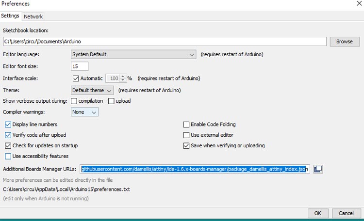
Step 3: Programming ATtiny85 Using Arduino IDE:
To program the ATtiny85 with Arduino IDE, first, we need to add the ATtiny85 Support to Arduino IDE. For that, go to File > Preferences and add the below link in the Additional Boards Manager URLs and click ‘OK.’
After that, go to Tools > Board > Board Manager and search for ‘attiny’ and install the latest version.
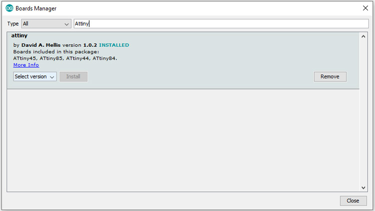
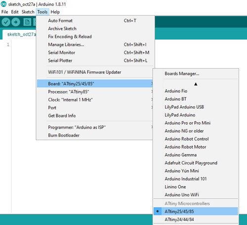
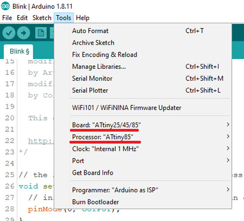
After installing it, now you would be able to see a new entry in the Board menu titled 'Attiny25/45/85'.
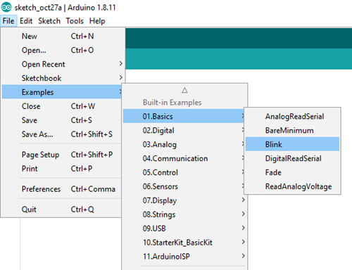
Now, go to File > Examples > Basics and open the Blink example.
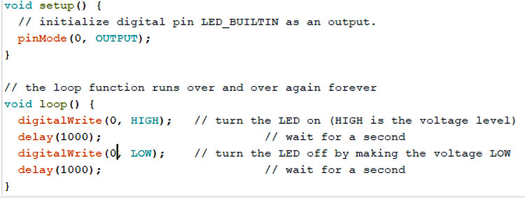
Change the pin number there from LED_BUILTIN to 0.
Now go back to Tools -> Board and select “Attiny25/45/85”, then select ATtiny85 under Tools > Processor.
Now, go ahead and upload the code. If the LED connected to Pin 0 of Attiny85 IC blinks, then the code is uploaded successfully.
This is how you can program the ATtiny85 Microcontroller Chip using Arduino IDE and Arduino Uno. A working video is given below. If you have any questions, leave them in the comment section. You can also post your technical queries on our Electronics Forum to get better insights.
Comments
Thank you greatly for this…
Thank you greatly for this tut. It got me 95% of the way there... I never ran arduino isp example sketch which solved my last issue. Point of note, the tut's wiring diagram makes it look to put in the led backwards. Otherwise, anyone else having issues ensure that:
-Run ArduinoIsp sketch
-Your breadboard/jumpers aren't shoddy. If you see flickering on your Arduinos led when you move your 5v line, do yourself a favor and never use them again heh
-Upload the Blink program with 'Upload with Programmer' under sketch
I was able to burn the bootloader at a higher clock with this tut as well. Thanks again.

Thank you for a very clear step by step explanation. Unfortunately when I tried to follow your instructions it failed at almost the first step!
Going to File > Example > ArduinoISP the ISP was located and opened, BUT when up loaded it failed with the message 'Serial' was not declared in this scope. The section of code identified was
#ifdef SERIAL_PORT_USBVIRTUAL
#define SERIAL SERIAL_PORT_USBVIRTUAL
#else
#define SERIAL Serial This line highlighted
#endif
I am a complete novice in this matter so cannot hope to know what to do in order to successfully upload the code. In my limited experience I have only used <Serial.begin(9600);> in setup in order to monitor whats happening in a sketch using Serial.println( ). So a code section such as #ifdef to #endif is new to me as is <SERIAL.print((char)STK_UNKNOWN);> etc. So help please what should I do to successfully upload the ISP code?
I'm using Arduino 1.8.19 with an UNO R3
Thank you