

Over the past few years, IoT (Internet of Things) devices have become an indistinguishable part of our daily lives. From smart homes, smart bulbs to smart appliances; creators and developers are incorporating this technology to create a network of connected devices that makes our day-to-day life a little more exciting. All this has been made possible because of the ease of communication. There are many possible ways to communicate among devices, but in commercial and hobby products, a single protocol that is commonly used is Message Queuing Telemetry Transport (MQTT). We previously built a Voice-Controlled FM Radio using Arduino and Google Assistant that utilizes MQTT to communicate with the NodeMCU board. Do check it out if that sounds interesting to you.
In this project, we will be using a free and popular Eclipse MQTT broker and learn how to connect an IoT device (in our case, it’s a NodeMCU module) to an MQTT broker and transfer data among the MQTT broker and NodeMCU.
What is MQTT Protocol?
Before we proceed any further, it’s better to have a clear idea about the MQTT (Message Queuing Telemetry Transport) protocol. It is a lightweight messaging protocol that uses the publish/subscribe method and translates messages between multiple devices. Using MQTT protocol, we can also send/receive data and control various output devices, like read sensor data, etc. It's developed on top of TCP, which is why it's faster than similar protocols like HTTP. Other than that, it has many other advantages over other protocols like its very lightweight, so it doesn't consume excess memory, it can work with very less network bandwidth, on top of that, it has a robust security protocol inbuilt. These features make it suitable for many applications.
How MQTT Works?
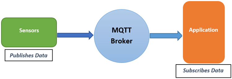
In order to understand the working of the MQTT protocol, we just need to understand three basic things; the above diagram shows that. Also, we have explained it below in the article.
MQTT Client:
An MQTT client is any device (it can be a microcontroller or a server) that runs MQTT functions and communicates with a central server, which is known as the “broker.” The broker handles the data communication between the connected clients.
MQTT Publisher:
When a client wants to send any information, the client is known as a “Publisher”. The publisher will publish the information on a particular topic. “Topic” is a path where we can publish/subscribe messages. The broker then sends the information published by the user to the clients (also known as Subscriber) that have subscribed to that specific topic.
MQTT Subscriber:
The MQTT Subscriber subscribes to topics on an MQTT broker to read the messages sent by the broker.
The Eclipse Mosquitto broker
Eclipse Mosquitto is an open-source MQTT broker, which is lightweight and is suitable for use on IoT devices for communication. The MQTT protocol provides a lightweight method of transferring information using a publish/subscribe model. If you want to learn more about the topic, you can visit the official mosquito website.
Setting up Eclipse Mosquitto broker:
In order to establish communication with the broker, we need to set it up first. In this project, an Android application is used to publish and subscribe to the information with the Broker. The following steps will give you a better idea of the setup process.
Step-1:
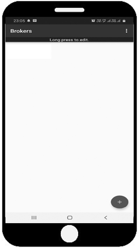
First, download any “MQTT client” application available in the Google Play Store / App Store and install it. In this project, an application named “MQTT client” is used, which looks like the image shown below.
Step-2:
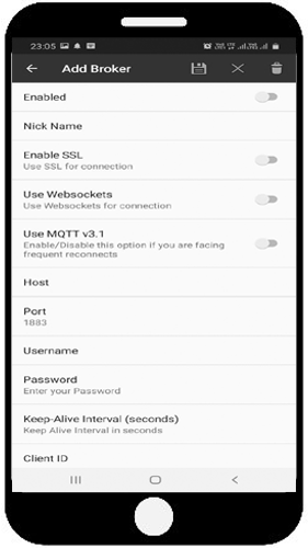
Click on the “+” sign to list the additional options in the application, where we are going to add a new broker. When the button is clicked, a new screen appears as shown below.
Step-3:
Thereafter, the details of the broker need to be filled in the required field. First, click on the option “Enabled” shown in the Application. In this project, the Eclipse MQTT broker is used, the details which are to be filled are given below:
Nick Name: Give a Name of Your Preference
Host: mqtt.eclipse.org
Port: 1883
Client ID: Give an ID of Your Preference
The above details need to be filled in their respective fields. All other fields are not necessary and can be left blank. After successful completion, click on the save button to save the Broker details.
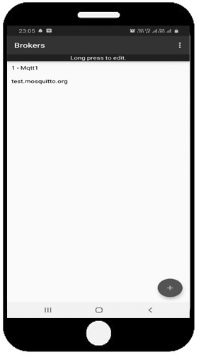
Once done, the android application setup process is over and now we can move on to the hardware side of things.
Components Required
A complete list of required parts is described below. As this circuit is simple, you can find all the necessary parts at your local hobby store.
- NodeMCU
- LED
- Breadboard
- Connecting wires
- Programming cable
Eclipse MQTT Test-Circuit - Schematic
The circuit diagram for the Basic MQTT project is given below:

Programming ESP8266 to Establish Communication with Broker
A simple Arduino code takes care of all the necessary communications between the MQTT broker and the NodeMCU. In this section, we will learn how this functionality works in detail.
Setup Arduino IDE and Upload the Code:
If you are uploading the code to the NodeMCU for the first time, you need to set-up the Arduino IDE first. To do that, just follow the simple instruction given below.
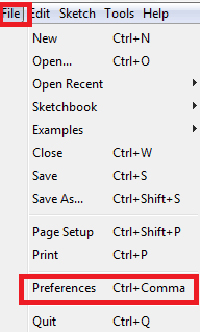
First, Open Arduino IDE, then go to File–>Preferences–>Settings.
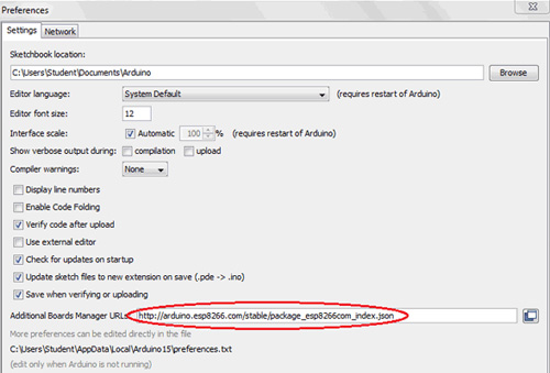
Next, copy the below URL and paste it in the ‘Additional Board Manager URL’ field, and click ‘Ok’. You can check the image below to know how we have done that.
Link: https://arduino.esp8266.com/stable/package_esp8266com_index.json
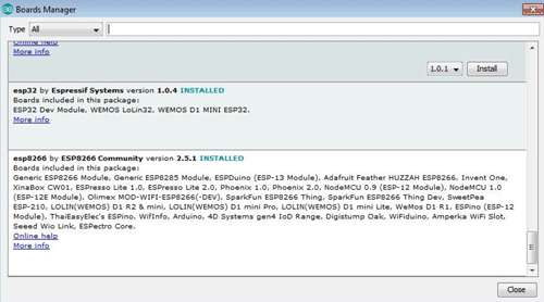
Next, go to Tools > Board > Boards Manager. In the Board's Manager window, Type ESP8266 in the search box and hit enter. Then select the latest version from the dropdown and click on install. The image below will give you a clear idea.
Finally, once the installation is completed, go to Tools ->Board -> and select NodeMCU 1.0(ESP-12E Module). Now, you can program NodeMCU with Arduino IDE. As we have finished setting up the Arduino IDE, we can now upload the complete code. But first, read on the quick explanation of the whole code.
Firstly, we have included “ESP8266WiFi.h” for using ESP8266 and “PubSubClient.h” for MQTT.
You can find the ESP8266 library prebuilt inside the Arduino library, but you need to download the PubSubClient library from its associated GitHub repository.
#include <ESP8266WiFi.h>
#include <PubSubClient.h>
Then, define the network credentials such as your Wi-Fi username and password. Replace your credentials in place of “admin” & “12345678” respectively.
const char* ssid = "admin";
const char* password =  "12345678";
Next, we need to configure the MQTT server. We have used the Eclipse MQTT server for this project, which is why the server address is given as “mqtt.eclipse.org”. But if you plan to use any other server like Mosquitto, Adafruit, then you can replace it with your specific server address and port number.
const char* mqtt_server = "mqtt.eclipse.org";
const int mqtt_port = 1883;
Next, the instances are created for class WiFiClient and PubSubClient, which will be used throughout the program.
WiFiClient espClient;
PubSubClient client(espClient);
In the setup() section, we call the WiFi.begin() first, calling this method will connect the ESP to your preferred HotSpot.
WiFi.begin(ssid, password);
Next, we check for a successful network connection using the WiFi.status() method. After a successful connection, a message is printed on Serial Monitor with the SSID of the connected network.
  while (WiFi.status() != WL_CONNECTED) {
    delay(500);
    Serial.println("Connecting to WiFi..");
  }
  Serial.print("Connected to WiFi :");
  Serial.println(WiFi.SSID());
Now, we need to create a broker. For that, we have used the setServer method; this method takes two arguments which we have predefined earlier. Now, if we want to receive messages from the server, we need to create a callback function. For that, we are using the setCallback(callback) method.
client.setServer(mqtt_server, mqtt_port);
client.setCallback(MQTTcallback);
Now, we have used the connect (clientID) function to connect to the ESP8266 client. Here clientID is the name of the client, and it must be unique. If it is connected, then a success message can be shown inside the serial monitor.
if (client.connect("ESP8266"))
    {
      Serial.println("connected");
    }
    else
    {
      Serial.print("failed with state ")
      Serial.println(client.state());
      delay(2000);
    }
Next, we call the client.subscribe(), a built-in MQTT function, which is used to subscribe to a particular topic. For this project, we have used “esp/test” as our subscriber name.
client.subscribe("esp/test");
Now, the MQTTcallback function is called to check whether any updated information is available or not. If new data is available, this function handles the received data and prints a message in the serial monitor with the original message and topic name where the message is received.
Next, we convert the messages into a string, so that it can be compared and checked for any triggering actions. In this project, an LED is turned ON/OFF using MQTT commands, as shown in the code below.
for (int i = 0; i < length; i++)
  {
    message = message + (char)payload[i];
  }
  Serial.print(message);
  if (message == "on")
  {
    digitalWrite(LED, HIGH);
  }
Finally, to publish the information on the topic. The client.publish() function is used. In this project, a push-button status is checked, if the button is pressed, then a message is published to a Topic “esp/test1” as shown below.
if(digitalRead(D1)==0))
  {
  client.publish("esp/test1", "Hello from ESP8266");
  }
  else;
client.loop();
Testing MQTT with ESP8266 using Arduino
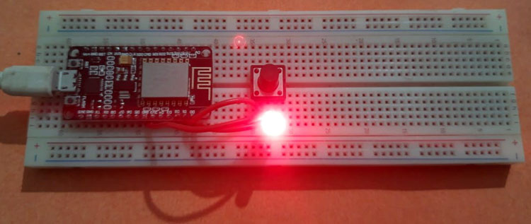
For our final testing, we are going to use the Android application, which we have set up earlier.
Open the MQTT client application, and make sure your mobile has an active internet connection. Also, the hotspot to which the NodeMCU is connected should have an active internet connection. Once everything is connected to the internet, we are going to send a “Hello from ESP8266” string from the ESP module, which will be reflected inside the Android app, and we will get a notification. Next, we will send a string from the Android app, which will turn ON an LED that is connected to the ESP8266 Node MCU board.
Step-1: (Subscribe to the Topic):
Click on the Saved MQTT option on App, which we have configured earlier. It will pop up a screen, where it is prompted to “Subscribe to a Topic”. We have previously configured the topic as “esp/test1”. So, in the Android app, we will write “esp/test1”. Click on Subscribe, doing so will present you with a screen like below, where it will be written like “No message received” from the particular Topic.
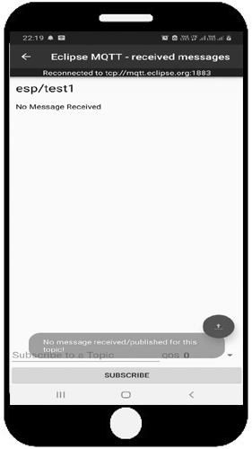
Now, click the button 'Connected' which is connected to the nodeMCU. Now as per our code, a message “Hello from ESP8266” will be published to the Topic and there will be a notification on the screen with the message received as shown below.

Step-2: Publish to the Topic:
Now to publish in the Topic, Click on the UP ARROW button of the Application, and it will open a screen as shown below.
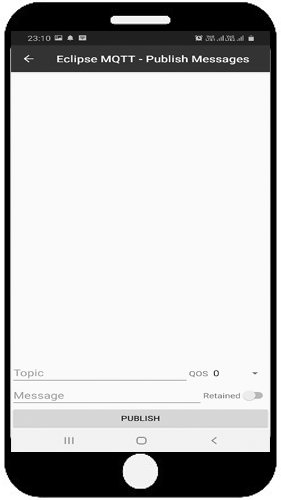
Now, In the Topic field, write “esp/test” and in the message field, write “on” or “off” to turn on and off the LED respectively. For example, if “on” is published to the Topic, then the LED will be turned on and if "off" is published to the Topic, then the LED will be turned off.
I hope you liked the article and learned something new. If you have any questions regarding this article, please feel free to comment below or you can use our forum instead.
#include <ESP8266WiFi.h>
#include <PubSubClient.h>
#define LED D0
const char* ssid = "admin";
const char* password =  "12345678";
const char* mqtt_server = "mqtt.eclipse.org";
const int mqtt_port = 1883;
WiFiClient espClient;
PubSubClient client(espClient);
void setup()
{
  pinMode(LED, OUTPUT);
  pinMode(D1,INPUT_PULLUP);
  Serial.begin(115200);
  WiFi.begin(ssid, password);
  while (WiFi.status() != WL_CONNECTED)
  {
    delay(500);
    Serial.println("Connecting to WiFi..");
  }
  Serial.print("Connected to WiFi :");
  Serial.println(WiFi.SSID());
  client.setServer(mqtt_server, mqtt_port);
  client.setCallback(MQTTcallback);
  while (!client.connected())
  {
    Serial.println("Connecting to MQTT...");
    if (client.connect("ESP8266"))
    {
      Serial.println("connected");
    }
    else
    {
      Serial.print("failed with state ");
      Serial.println(client.state());
      delay(2000);
    }
  }
  client.subscribe("esp/test");
}
void MQTTcallback(char* topic, byte* payload, unsigned int length)
{
  Serial.print("Message received in topic: ");
  Serial.println(topic);
  Serial.print("Message:");
  String message;
  for (int i = 0; i < length; i++)
  {
    message = message + (char)payload[i];
  }
  Serial.print(message);
  if (message == "on")
  {
    digitalWrite(LED, HIGH);
  }
  else if (message == "off")
  {
    digitalWrite(LED, LOW);
  }
  Serial.println();
  Serial.println("-----------------------");
}
void loop()
{
  if(digitalRead(D1)==0)
  {
  client.publish("esp/test1", "Hello from ESP8266");
  delay(1000);
  }
  else;
  client.loop();
}