
In this tutorial, we are going to interface an OLED display module with the Pico board. You will be able to perform an I2C communication on Raspberry Pi Pico at the end of this tutorial. Here, we are going to display some strings on an OLED display by using Micropython. We already have some articles and projects on the Interfacing of the OLED display. You can refer to those articles and projects to get a proper idea of the working of an OLED display.
Hardware Required
- 4pins I2C based 1.3 Inch 128×64 OLED display Module (SSD1306)
- Raspberry Pi Pico
- Breadboard
- Connecting Wires
Circuit Diagram to Interface SSD1306 OLED Display with Raspberry Pi Pico
You can refer the circuit connection of the Raspberry Pi Pico and OLED display module as shown below. The SDA pin of the OLED Display Module is connected to the GPIO16(Pin21) and the SCL pin is connected to the GPIO17(Pin22). The Vcc pin is connected to the 3.3v Pin of the Pico Board that is Pin36. The Ground pin of the Display module is connected to the Ground pin of the Pico board that is Pin38.

Library for OLED Display in MicroPython
At first, create a new folder where you want to save your code files. Then you need to download our complete GitHub repository on Raspberry Pi Pico Using MicroPython. Go to the “T3_Interfacing_An_OLED” folder. You need to copy the “main.py” and “ssd1306.py” files and then paste these files in the folder that you created to save your code files. So, we now have two files. The “main.py” file contains the code for displaying text and images. And the “ssd1306.py” is the library of the OLED display module. Before understanding the code, you need to perform an image to bitmap conversion to display an image on the OLED module. You can see another “img_to_bmp.py” file in the “T3_Interfacing_An_OLED” folder. You need a python environment to run this file. In my case, I have used Python3.6 to run this file.
Code Explanation of the img_to_bmp.py file
You need to install the following “PIL” library in your Python environment by using the “pip” command. The input_filename_with_path is containing the path of the file without extension. In my case, the image file and the img_to_bmp.py file are in the same folder. So, I mentioned only the name of the image file. The “Image.open(file_in)” is opening the targeted image file and then we are performing some image operation by using the transpose() and convert() functions. The save() function is used to save the converted image as an output file with the “.bmp” extension. Then the Image.open(file_out,mode='r') is used to open the “bmp” file and io.BytesIO() function is used to read the bitmaparray of the image. The img_bytes is used to store the bitmap array which we will get at the output. The print(img_bytes) will print the byte array of the input image. We need to copy this byte array for further reference in the “main.py” file. The print('Image Resolution: ({0},{1})'.format(img.width,img.height)) will print the resolution of the image. We need to use this resolution in our “main.py” file. Make sure that the resolution is not large. You can use any online converter to reduce the image resolution.
import io
from PIL import Image
input_filename_with_path = "rpilogo1"
file_in = input_filename_with_path + ".png"
file_out = input_filename_with_path+".bmp"
img = Image.open(file_in)
img = img.transpose(Image.FLIP_LEFT_RIGHT)
threshold = 65
func = lambda x : 255 if x > threshold else 0
img = img.convert('L').point(func,mode='1')
img.save(file_out)
img = Image.open(file_out,mode='r')
img_bytes = io.BytesIO()
img.save(img_bytes,format='BMP')
img_bytes = img_bytes.getvalue()
print("Copy this bitmap array:")
print('\n')
print(img_bytes)
print('\n')
print('Image Resolution: ({0},{1})'.format(img.width,img.height))
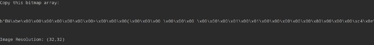
The above image is the output of the img_to_bmp.py. In my case, I have already converted the resolution of the input image into a 32x32 size.
So, now we have the byte array of the image. Let’s understand the code of the “main.py” file below. We are using the “machine” library to perform the basic hardware operations with the help of MicroPython. Then we are using the “ssd1306” library that we recently added to the Raspberry Pi Pico board. The “utime” library is used to access the inbuilt time feature of the raspberry pi pico board. The framebuf,sys library is used to perform the byte array operations.
from machine import Pin, I2C
from ssd1306 import SSD1306_I2C
import utime
import framebuf,sys
WIDTH  = 128                                            # oled display width
HEIGHT = 64
The following image_byte_arr variable contains the byte array (bitmap array) of the image to be displayed. Paste the byte array which you have copied from the output of the img_to_bmp.py file. Then mention the same width and height of the image as per the output of the img_to_bmp.py file.
image_byte_arr = b'BM\xbe\x00\x00\x00\x00\x00\x00\x00>\x00\x00\x00(\x00\x00\x00 \x00\x00\x00 \x00\x00\x00\x01\x00\x01\x00\x00\x00\x00\x00\x80\x00\x00\x00\xc4\x0e\x00\x00\xc4\x0e\x00\x00\x02\x00\x00\x00\x02\x00\x00\x00\x00\x00\x00\x00\xff\xff\xff\xff\xff\xfc?\xff\xff\xfb\xcf\xff\xff\xe7\xf7\xff\xff\xc7\xf1\xff\xffs\xc6\x7f\xfe\xf1\xcf\xbf\xfd\xf7\xef\xbf\xfd\xf7\xf7\xdf\xff\xff\xf7\xdf\xfb\xef\xf3\xdf\xf9\xc7\xf1\x8f\xf6\x13\xeco\xf7|>w\xf7~\x7fw\xf7\xfe\x7fw\xf7\xff\x7fo\xfb\x7f\x7fo\xfc~~\x1f\xfd\xbc=\xff\xff\xe3\xe3\xbf\xfe\xf7\xf7\xbf\xff\x7f\xff\x7f\xff3\xe4\xff\xffx\x1f\x7f\xfe\xfc?\xbf\xfd\xfe?\xff\xfb\xff\x7f\xdf\xfb\xff\x7f\xdf\xfb\xfe\x7f\xef\xfb\xff\xbf\xef\xf9\xfb\xdf\x9f\xff\x0f\xf0\xff'
image_width = 32
image_height = 32
The following I2C() function is used to initialize the I2C communication. This function takes the number of the I2C channel as we have 2 channels of I2C in the pico board. In my case, I am using the I2C0. If you are using I2C1, then change the first parameter from 0 to 1. The next two parameters are used to indicate the SCL and SDL pins for the communication. In my case, I am using the 17 and 16 pins for SCL and SDL, respectively. Then the next parameter of the I2C function is refer to the I2C communication frequency. The i2c.scan() is used to get the targeted device address.
#OLED I2C Configuration
i2c = I2C(0, scl=Pin(17), sda=Pin(16), freq=200000) #Init I2C using pinsGP17&GP16 (defaultI2C0 pins)
print("I2C Address      : "+hex(i2c.scan()[0]).upper()) # Display device address
print("I2C Configuration: "+str(i2c))                   # Display I2C config
The SSD1306_I2C() function is used to initialize the OLED Display and store it in “oled” as an object. This function usually takes the width, height and the mode of the communication of the device. Then we have some predefined functions in the ssd1306 library which can be called by using the “oled” object. The oled.fill(0) is used to clear the screen.
oled = SSD1306_I2C(WIDTH, HEIGHT, i2c) # Init oled display
The following displayText() function is used to display the text on the OLED. You need to pass the text, position, clear_oled and the show_text parameter into the function. The position is set to (0,0) by default. But you can change the position of the text by this position parameter. The position of the text must be in the tuple format (for example: (x,y)). The clear_oled and the show_text is set to True by default but you can change the status by set these variables into False.
#OLED Text display Function
def displayText(text, position=(0,0),clear_oled=True,show_text=True):
    if clear_oled:
        oled.fill(0) # Clear the oled display in case it has junk on it.
    oled.text(text,position[0],position[1]) # dispaying text
    if show_text:
        oled.show()  # Updating the display
The below displayImage() function is used to display the image on the OLED display. This function has image_byte_array, image_resolution,position,clear_oled and show_img parameters. We need to pass the image_byte_arr variable in place of the image_byte_array parameter. Then the image_resolution is containing the image_width and the image_height must be in the tuple format. (example: (image_width, image_height)). Then you can pass the image position on OLED by using the position parameter. Again, the position needs to be in tuple format and it is set to (0,0) by default. The clear_oled and show_img parameters are set to False and True, respectively. We can change these status as per our need in the future. The bytearray() function is used to take the bitmap of the image. Then the framebuf.FrameBuffer() function is used to store the every bit of the bitmap. The frame buffer has several types. We are using the MONO_HMSB mode of the framebuffer. Then we need to use the oled.blit() function to display the frame of the image on the OLED module.
#OLED Image display function
def displayImage(image_byte_array, image_resolution,position=(0,0),clear_oled=False,show_img=True):
    img = bytearray(image_byte_array)
    img = bytearray([img[i] for i in range(len(img)-1,-1,-1)])
    frame = framebuf.FrameBuffer(img, image_resolution[0], image_resolution[1], framebuf.MONO_HMSB) # frame buffer types: MONO_HLSB, MONO_VLSB, MONO_HMSB
    if clear_oled:
        oled.fill(0) # clear the OLED
        print("clear")
    if show_img:
        oled.blit(frame, position[0],position[1]) # show the image at location (x=0,y=0)
        oled.show()
        print("display")
The following code is used to display texts on the OLED and scroll those texts on the OLED. I called the displayText() function for two times under the for loop and passed the text1 and the text2 as string with their corresponding positions “(x,0)” and (WIDTH-x,20). I set the clear_oled as False and show_text as True for text1 and for text2 I set the clear_oled as True and show_text as True. It will allow us to display the texts on the OLED in every iteration. When the value of the “x” variable will reach to the end of the iteration that is the WIDTH of the OLED, then the for loop will break.
#Scrolling Text on OLED
text1 = "Welcome to"
text2 = "CircuitDigest"
for x in range(0, WIDTH):
    displayText(text1,(x,0),clear_oled=False,show_text=True)
    displayText(text2,(WIDTH-x,20),clear_oled=True, show_text=True)
    if x == WIDTH:
        break
    else:
        x+=5
Under the while loop, below I used for loop to animate the Image with text. I used the displayImage function to display the image. I provided the image_byte_arr, (image_width,image_height), (x,y), and clear_oled parameters. Here the “(x,y)” is the position of the image which are in the tuple format. The image_width and the image_height is representing the resolution of the image in the tuple format. Then I set the clear_oled as False and I did not set the show_img variable because it is set to True by default. So, you can also use the both displayImage() and the displayText() function to display image and text on OLED, respectively.
while True:
    y=0
    text = "Interfacing OLED"
    oled.fill(0)
    #Animating Text And Image Horizontaly
    for x in range(0,WIDTH-image_width):
        displayImage(image_byte_arr,(image_width,image_height),(x,y),clear_oled=False)
        displayText(text,(x,y+40),clear_oled=False,show_text=True)
        if x == (WIDTH-image_width)-1:
            break
        else:
            x+=2
            oled.fill(0)
    for x in range(WIDTH-image_width,-1,-1):
        displayImage(image_byte_arr,(image_width,image_height),(x,y),clear_oled=True)
        displayText(text,(x,y+40),clear_oled=False,show_text=True)
        if x == 0:
            break
        else:
            x-=2
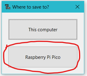
Now, open the “main.py” file and the “ssd1306.py” file in the Thonny IDE. At first you need to save the “ssd1306.py” file on the Pico board by pressing “ctrl+shift+s” of your keyboard. Make sure that you have connected your Pico board with your Laptop before saving the files. When you will save the code it will show you a popup as the below image. You need to select the Raspberry Pi Pico and then name the file as “ssd1306.py” and click on save. Then do the same procedure for the “main.py” file. This procedure allows you to run the program when the Pico will be powered up.
Working demo of the Interfacing of the OLED Display Raspberry Pi Pico
In the following video, I have explained all the steps and codes in detail. You can refer the following video to interface an OLED with the Raspberry Pi Pico board.
OLED:
# Display Image & text on I2C driven ssd1306 OLED display
from machine import Pin, I2C
from ssd1306 import SSD1306_I2C
import utime
WIDTH = 128 # oled display width
HEIGHT = 64 # oled display height
i2c = I2C(0, scl=Pin(17), sda=Pin(16), freq=200000) # Init I2C using pins GP8 & GP9 (default I2C0 pins)
print("I2C Address : "+hex(i2c.scan()[0]).upper()) # Display device address
print("I2C Configuration: "+str(i2c)) # Display I2C config
oled = SSD1306_I2C(WIDTH, HEIGHT, i2c) # Init oled display
# Clear the oled display in case it has junk on it.
oled.fill(0)
# Add some text
oled.text("Welcome",5,8)
oled.text("To",15,8)
oled.text("CIRCUIT DIGEST",8,25)
# Finally update the oled display so the image & text is displayed
oled.show()
utime.sleep(1)
counter = 0
while True:
oled.fill(0)
utime.sleep(0.2)
oled.text("Counter:",5,8)
oled.text(str(counter),15,8)
oled.show()
utime.sleep(2)
counter+=1
SSD1306:
# MicroPython SSD1306 OLED driver, I2C and SPI interfaces
from micropython import const
import framebuf
# register definitions
SET_CONTRAST = const(0x81)
SET_ENTIRE_ON = const(0xA4)
SET_NORM_INV = const(0xA6)
SET_DISP = const(0xAE)
SET_MEM_ADDR = const(0x20)
SET_COL_ADDR = const(0x21)
SET_PAGE_ADDR = const(0x22)
SET_DISP_START_LINE = const(0x40)
SET_SEG_REMAP = const(0xA0)
SET_MUX_RATIO = const(0xA8)
SET_COM_OUT_DIR = const(0xC0)
SET_DISP_OFFSET = const(0xD3)
SET_COM_PIN_CFG = const(0xDA)
SET_DISP_CLK_DIV = const(0xD5)
SET_PRECHARGE = const(0xD9)
SET_VCOM_DESEL = const(0xDB)
SET_CHARGE_PUMP = const(0x8D)
# Subclassing FrameBuffer provides support for graphics primitives
# http://docs.micropython.org/en/latest/pyboard/library/framebuf.html
class SSD1306(framebuf.FrameBuffer):
def __init__(self, width, height, external_vcc):
self.width = width
self.height = height
self.external_vcc = external_vcc
self.pages = self.height // 8
self.buffer = bytearray(self.pages * self.width)
super().__init__(self.buffer, self.width, self.height, framebuf.MONO_VLSB)
self.init_display()
def init_display(self):
for cmd in (
SET_DISP | 0x00, # off
# address setting
SET_MEM_ADDR,
0x00, # horizontal
# resolution and layout
SET_DISP_START_LINE | 0x00,
SET_SEG_REMAP | 0x01, # column addr 127 mapped to SEG0
SET_MUX_RATIO,
self.height - 1,
SET_COM_OUT_DIR | 0x08, # scan from COM[N] to COM0
SET_DISP_OFFSET,
0x00,
SET_COM_PIN_CFG,
0x02 if self.width > 2 * self.height else 0x12,
# timing and driving scheme
SET_DISP_CLK_DIV,
0x80,
SET_PRECHARGE,
0x22 if self.external_vcc else 0xF1,
SET_VCOM_DESEL,
0x30, # 0.83*Vcc
# display
SET_CONTRAST,
0xFF, # maximum
SET_ENTIRE_ON, # output follows RAM contents
SET_NORM_INV, # not inverted
# charge pump
SET_CHARGE_PUMP,
0x10 if self.external_vcc else 0x14,
SET_DISP | 0x01,
): # on
self.write_cmd(cmd)
self.fill(0)
self.show()
def poweroff(self):
self.write_cmd(SET_DISP | 0x00)
def poweron(self):
self.write_cmd(SET_DISP | 0x01)
def contrast(self, contrast):
self.write_cmd(SET_CONTRAST)
self.write_cmd(contrast)
def invert(self, invert):
self.write_cmd(SET_NORM_INV | (invert & 1))
def show(self):
x0 = 0
x1 = self.width - 1
if self.width == 64:
# displays with width of 64 pixels are shifted by 32
x0 += 32
x1 += 32
self.write_cmd(SET_COL_ADDR)
self.write_cmd(x0)
self.write_cmd(x1)
self.write_cmd(SET_PAGE_ADDR)
self.write_cmd(0)
self.write_cmd(self.pages - 1)
self.write_data(self.buffer)
class SSD1306_I2C(SSD1306):
def __init__(self, width, height, i2c, addr=0x3C, external_vcc=False):
self.i2c = i2c
self.addr = addr
self.temp = bytearray(2)
self.write_list = [b"\x40", None] # Co=0, D/C#=1
super().__init__(width, height, external_vcc)
def write_cmd(self, cmd):
self.temp[0] = 0x80 # Co=1, D/C#=0
self.temp[1] = cmd
self.i2c.writeto(self.addr, self.temp)
def write_data(self, buf):
self.write_list[1] = buf
self.i2c.writevto(self.addr, self.write_list)
class SSD1306_SPI(SSD1306):
def __init__(self, width, height, spi, dc, res, cs, external_vcc=False):
self.rate = 10 * 1024 * 1024
dc.init(dc.OUT, value=0)
res.init(res.OUT, value=0)
cs.init(cs.OUT, value=1)
self.spi = spi
self.dc = dc
self.res = res
self.cs = cs
import time
self.res(1)
time.sleep_ms(1)
self.res(0)
time.sleep_ms(10)
self.res(1)
super().__init__(width, height, external_vcc)
def write_cmd(self, cmd):
self.spi.init(baudrate=self.rate, polarity=0, phase=0)
self.cs(1)
self.dc(0)
self.cs(0)
self.spi.write(bytearray([cmd]))
self.cs(1)
def write_data(self, buf):
self.spi.init(baudrate=self.rate, polarity=0, phase=0)
self.cs(1)
self.dc(1)
self.cs(0)
self.spi.write(buf)
self.cs(1)
OLED:
OLED:
OLED:
