
In this tutorial, we will learn to Guide you about how you can interface a heartbeat sensor with an Arduino to measure live-heartbeat of any person. We will be also interfacing an OLED display to the Arduino to show the real-time values on its screen.
Components required for this Project are
- Arduino uno
- Heartbeat Sensor
- OLED
- Jumper wires
We have previously interfaced same heart rate sensor with Arduino and displayed the values online using ThingSpeak.
Heartbeat Sensor Pinout
The Heartbeat sensor consists of 3 pins- VCC, GND and Analog Output Pin.

VCC - It is the power supply pin of the sensor module.
GND - It is the ground pin of the sensor module.
Signal - It is the Analog Output Signal Pin of the sensor module.
Working of Heartbeat Sensor
The heartbeat sensor operates on the principle of detecting the subtle changes in blood flow through the skin caused by the expansion and contraction of blood vessels with each heartbeat. The sensor typically uses an optical or electrical method to capture these changes.

In an optical sensor like the one we are using, a light source, usually an LED, emits light that penetrates the skin and blood vessels. A photodetector then measures the amount of light that is absorbed or reflected back. As the blood vessels expand and contract with each heartbeat, the amount of light absorbed or reflected changes, allowing the sensor to calculate the heart rate. This method of heartbeat detection through light is called Photoplethysmogram.
Parts of a Heartbeat Sensor
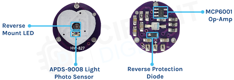
At the front of the heartbeat sensor we have the photodiode and the IR Leds to detect the heartbeat. At the back of the sensor, we have the op-amp to provide gain to the circuit and reverse voltage protection diode to protect circuit from ESD and reverse voltage protection. A few additional capacitors and resistors are added in the circuit as RC filters to reduce any external noise.
Commonly Asked Questions about Heartbeat Sensor Module
Are heartbeat sensor modules safe to use?
Yes, heartbeat sensor modules are generally safe to use. They emit low levels of non-harmful light for measurement, similar to the technology used in pulse oximeters and medical devices.
Can heartbeat sensor modules be used for medical purposes?
While heartbeat sensor modules can provide heart rate data, they may not always meet the stringent accuracy and regulatory requirements of medical-grade devices. They are often used for fitness and wellness applications rather than medical diagnosis.
Do heartbeat sensor modules work for people of all ages and skin tones?
Heartbeat sensor modules can work for people of different ages and skin tones. However, variations in skin color and texture may affect the ease of measurement. Some sensors may be better suited for specific skin types or conditions.
Circuit Diagram for Pulse Sensor Module

The Heartbeat Sensor module circuit diagram includes several essential components. At the forefront, there is a crucial 10uF filter capacitor, followed by a Green LED and a 470R resistor. This resistor serves as a current limiter for the sensor module. The circuit receives its power through a diode, which serves a dual purpose: it guards against reverse polarity and shields the circuit from transients.
Beyond the diode, the power distribution occurs between two key components: the MCP6001 operational amplifier and the APDS-9008 photodiode sensor IC. The sensor IC produces a low-amplitude and noisy output signal. To address this, a series of RC low-pass filters are employed to clean the signal. Subsequently, the op-amp amplifies the filtered signal, making it suitable for processing by a microcontroller.
Circuit Diagram of Arduino Heartbeat Sensor Interface

Connect the VCC (power) and GND (ground) pins of the heartbeat sensor to the 5V and GND pins on the Arduino, respectively. Connect the Analog OUT (signal) pin of the heartbeat sensor to one of the analog input pins on the Arduino (e.g., A0).
Arduino Code for Interfacing Heartbeat Sensor Module with Arduino
Here’s the code explanation for the complete tutorial. You can find the complete code at the absolute bottom of the blog.
int a = 0;
int lasta = 0;
int lastb = 0;
int LastTime = 0;
int ThisTime;
bool BPMTiming = false;
bool BeatComplete = false;
int BPM = 0;
These lines declare various integer and boolean variables used in the program.
a, lasta, and lastb are used for keeping track of values and positions related to the OLED display (which has been removed from your code).
LastTime and ThisTime are used to measure time intervals for calculating BPM (beats per minute).
BPMTiming and BeatComplete are boolean flags used to control BPM calculation.
BPM stores the calculated heart rate in beats per minute.
#define UpperThreshold 520
#define LowerThreshold 510
These lines define two constants UpperThreshold and LowerThreshold with specific values. These thresholds are used to determine when a heartbeat is detected based on the sensor's output. You may need to adjust these values depending on your sensor and environment.
void setup() {
  Serial.begin(9600);
}
This setup() function is called once when the Arduino starts. It initializes the serial communication with a baud rate of 9600, allowing you to send data from the Arduino to the Serial Monitor in the Arduino IDE.
void loop() {
  ThisTime = millis();
  int value = analogRead(0);
The loop() function is the main program loop that runs continuously after the setup() function. It first records the current time using millis() and reads an analog value from pin 0 (analogRead).
int b = 60 - (value / 16);
It calculates a value b based on the analog reading. This calculation appears to be related to the removed OLED display code, so it may not have a specific function in the current code.
  if (value > UpperThreshold) {
    if (BeatComplete) {
      BPM = ThisTime - LastTime;
      BPM = int(60 / (float(BPM) / 1000));
      BPMTiming = false;
      BeatComplete = false;
      tone(8, 1000, 250);
    }
    if (BPMTiming == false) {
      LastTime = millis();
      BPMTiming = true;
    }
  }
This section of code checks if the value from the sensor is greater than the UpperThreshold. If it is, it enters a block of code.
The inner if-statement checks if BeatComplete is true, indicating that a complete heartbeat cycle has occurred.
If a complete cycle has occurred, it calculates the time between heartbeats in milliseconds and converts it to BPM.
It then sets some flags and generates a tone using the tone function on pin 8.
The next if-statement checks if BPMTiming is false, indicating the start of a new heartbeat cycle. It records the current time in LastTime and sets BPMTiming to true.
  if ((value < LowerThreshold) & (BPMTiming))
    BeatComplete = true;
This section checks if the value falls below the LowerThreshold and if BPMTiming is true, indicating the end of a heartbeat cycle. If both conditions are met, it sets BeatComplete to true.
  Serial.println(BPM);
  a++;
}
Finally, the code prints the calculated BPM to the Serial Monitor and increments the a variable. This BPM value will continuously update as the loop runs.
Code for Arduino, Heartbeat Sensor and OLED Interfacing
The complete code for the project is as follows. You can copy, paste and upload the code on your arduinp board.
#include <Adafruit_SSD1306.h>
#define OLED_Address 0x3C // 0x3C device address of I2C OLED. Few other OLED has 0x3D
Adafruit_SSD1306 oled(128, 64); // create our screen object setting resolution to 128x64
int a=0;
int lasta=0;
int lastb=0;
int LastTime=0;
int ThisTime;
bool BPMTiming=false;
bool BeatComplete=false;
int BPM=0;
#define UpperThreshold 520
#define LowerThreshold 510
void setup() {
oled.begin(SSD1306_SWITCHCAPVCC, OLED_Address);
oled.clearDisplay();
oled.setTextSize(2);
Serial.begin(9600);
}
void loop() {
if(a>127) {
oled.clearDisplay();
a=0;
lasta=a;
}
ThisTime=millis();
int value=analogRead(0);
Serial.println(value);
oled.setTextColor(WHITE);
int b=60-(value/16);
oled.writeLine(lasta,lastb,a,b,WHITE);
lastb=b;
lasta=a;
if(value>UpperThreshold) {
if(BeatComplete) {
BPM=ThisTime-LastTime;
BPM=int(60/(float(BPM)/1000));
BPMTiming=false;
BeatComplete=false;
tone(8,1000,250);
}
if(BPMTiming==false) {
LastTime=millis();
BPMTiming=true;
}
}
if((value<LowerThreshold)&(BPMTiming))
BeatComplete=true;
oled.writeFillRect(0,50,128,16,BLACK);
oled.setCursor(0,50);
oled.print("BPM:");
oled.print(BPM);
oled.display();
a++;
}
Working Demonstration of the Project
Here’s how the final project output might look like.
Projects using Arduino and Pulse Sensor Module

If you are interested in learning PIC Microcontrollers and its working, this project can be what you are looking for, because in this project we have use a PIC microcontroller and a generic Pulse Sensor to build a heart rate monitoring system that uses the ADC on the PIC microcontroller to process the data.

If you are searching some IoT project Ideas then this project could be for you, because in this project we have used one of our favourite microcontroller Arduino and a Pulse Sensor to build a Heart Beat Monitoring System that is able to send the data to a thingspeak server instantaneously.

If you are looking for some simple IoT related project on the internet, this project can be an interesting one for you because in this project we have used a NodeMCU microcontroller and a Pulse Sensor to build a Painter Monitoring System that can come in handy in emergency situations.
int a = 0;
int lasta = 0;
int lastb = 0;
int LastTime = 0;
int ThisTime;
bool BPMTiming = false;
bool BeatComplete = false;
int BPM = 0;
#define UpperThreshold 520
#define LowerThreshold 510
void setup() {
Serial.begin(9600);
}
void loop() {
ThisTime = millis();
int value = analogRead(0);
int b = 60 - (value / 16);
if (value > UpperThreshold) {
if (BeatComplete) {
BPM = ThisTime - LastTime;
BPM = int(60 / (float(BPM) / 1000));
BPMTiming = false;
BeatComplete = false;
tone(8, 1000, 250);
}
if (BPMTiming == false) {
LastTime = millis();
BPMTiming = true;
}
}
if ((value < LowerThreshold) & (BPMTiming))
BeatComplete = true;
Serial.println(BPM);
a++;
}
