

CC3D (Copter control 3) is a flight controller, which is developed by Open Pilot and is completely open-source. In this tutorial, we are going to interface the CC3D flight controller with the NEO-6M GPS module. GPS is used in drones for many purposes like position hold, delivery, return to position, and many more but the CC3D flight controller does not support the return to base and position hold functionalities as it does not have enough memory for that. The only reason for employing GPS is for telemetry via radio modems (OPLink) or to relay GPS position to an OSD device. In this tutorial, we will see how to set up a GPS module using the TTL module and after that, we will interface the CC3D flight controller with the GPS module (Neo-6m).
Prerequisite
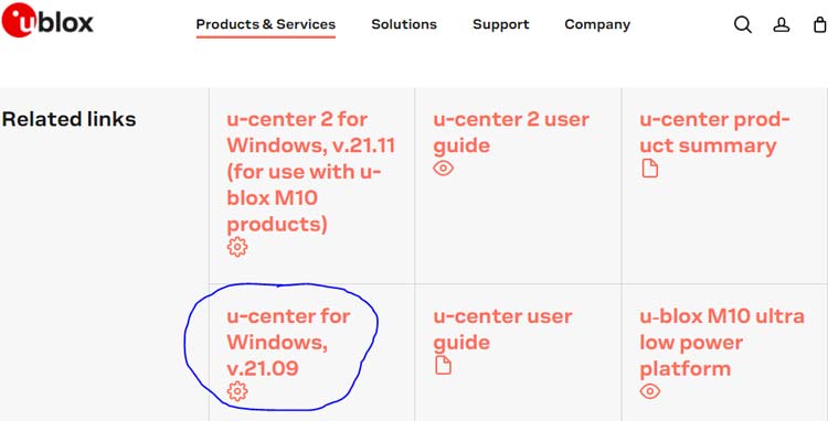
First, you have to download U center software. U-center is a powerful GNSS (Global navigation satellite system) evaluation and visualization tool that enables end-users to evaluate and test the navigation and positioning performance of u-blox GNSS positioning chips and modules. You can download the u-center for windows (v.21.09) by using this link. In the below image, you can see the blue circled downloadable link.
One thing you should remember is that this software is for only windows. It does not support Linux and Mac.
Components Required for Interfacing GPS with CC3D Flight Controller
- Neo-6m GPS module with antenna
- USB to TTL module
- PC with Windows OS
- Jumper wires
- U-center v21.09 software
Configuring GPS for CC3D Flight Controller
After downloading the u-center v.21.09, you need to install it. And follow the below steps to configure your GPS.
Step-1 Connect USB to TTL module with Neo-6m GPS according to the given table and circuit diagram. You have to do a serial connection between the GPS module and USB to the TTL module.

|
USB to TTL Module |
GPS Module |
|
+5V |
Vcc |
|
GND |
GND |
|
TXD |
RX |
|
RXD |
TX |
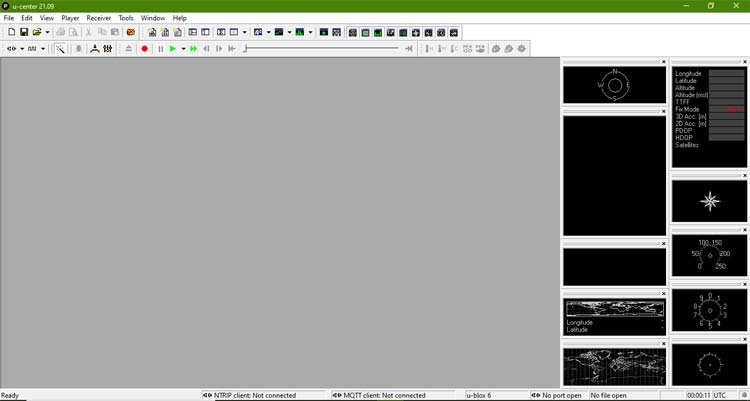
Step-2 After stabilizing the connection between the TTL module and GPS. Now, insert TTL module USB in your PC and open the U-center v.21.09 software. You will see the below screen on your PC.
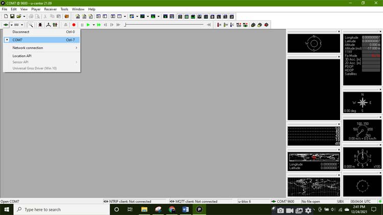
Step-3 Now, select the COM port for your GPS module. COM port option will be converted into green color after stabilizing the connection. If you are not able to see your COM port in this connection then you have to install a driver for it.
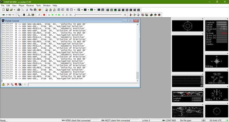
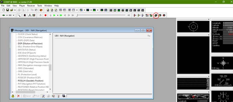
Step-4 Go to the View option and click on the Packet Console option. You should see message output from your GPS in the packet console window. If it is not showing any GPS output then try to connect it again and follow the same process.
Step-5 Go to the View option and click on the Configuration View option. Now, click on CFG (configuration) option on the left-hand side and select the Revert to default configuration option.
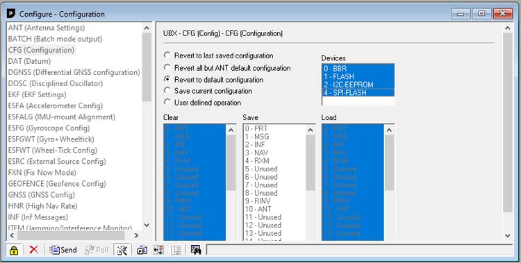
Now click on the send option at the bottom of the configuration window.
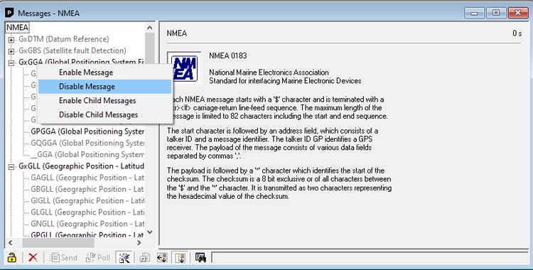
Step-6 Go to the View option and select the Message View option. Disable all the active NMEA messages.
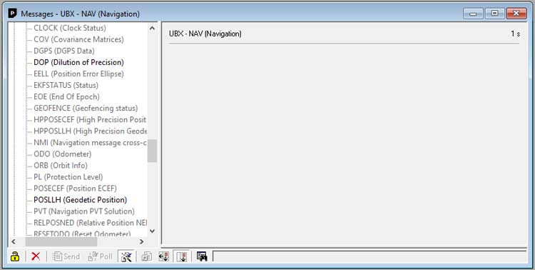
Go to the UBX option and enable the following in NAV (navigation) and NAV2 options.
POSLLH
DOP
SOL
VELNED
Now, save the current configuration by clicking on save current receiver configuration at the top menu bar. You can see the save button in the red circle.
Note- By using this configuration we cannot display the GPS plugin because GPS does not send SVINFO messages. CC3D flight controller works only with the minimum messages (VELNED, SOL, DOP, POSLLH).
Step-7 Go to the View option and select the Configuration View option. Scroll down and select the PRT (ports) option. Give the Target, Protocol in, Protocol out, and Baud rate values according to the below image.
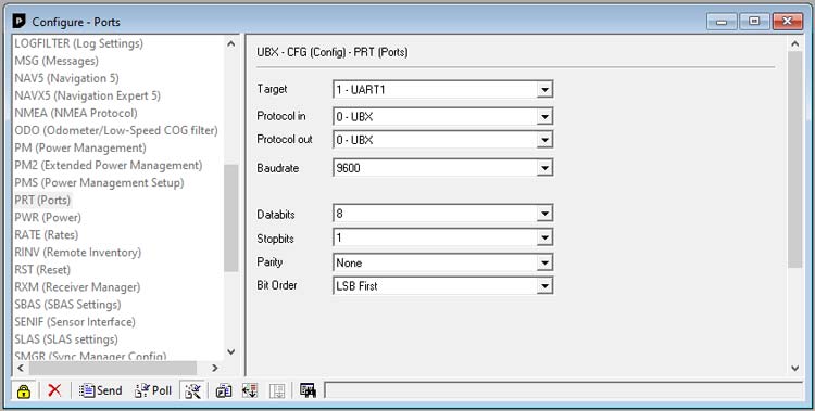
Note- You can select 19200 or 9600 baud rate for the CC3D flight controller.
Now click on the send option at the bottom of the configuration window.
Step-8 Now, go to the RATE (rates) option in the left column and select the Time source and Measurement Period according to the below image.
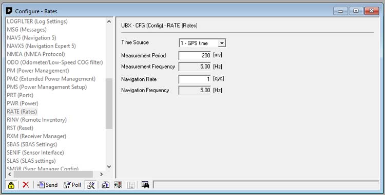
Now click on the send option at the bottom of the configuration window.
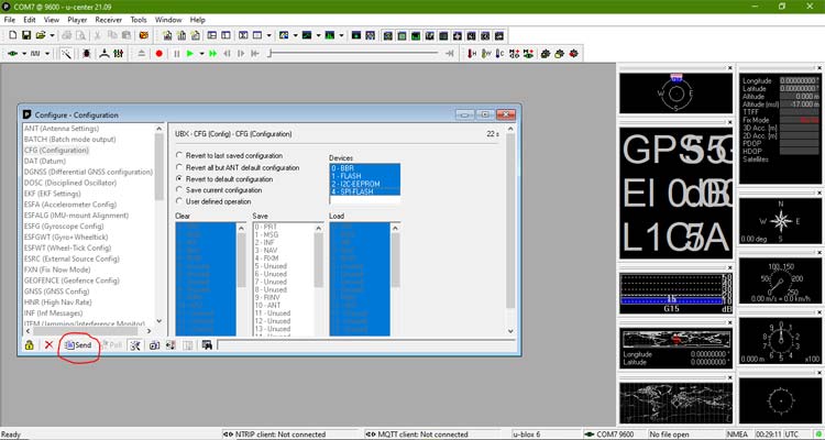
Step-9 Go to the CFG option and select the Save current configuration option. All devices should be selected in blue.
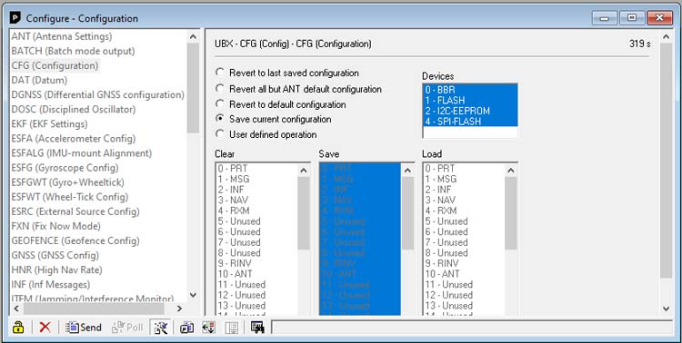
Now click on the send option at the bottom of the configuration window. After this remove the TTL module from your PC.
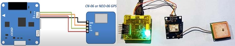
Step-10 After configuring the Software part now connect the NEO-6M GPS module with the main port of the CC3D flight controller as shown in the below image and connect the CC3D flight controller with your PC by using a micro-USB cable.
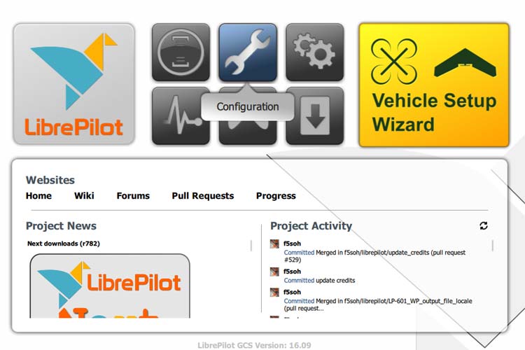
Step-11 Now, open the liber pilot GCS (ground control station) software and click on the configuration option.
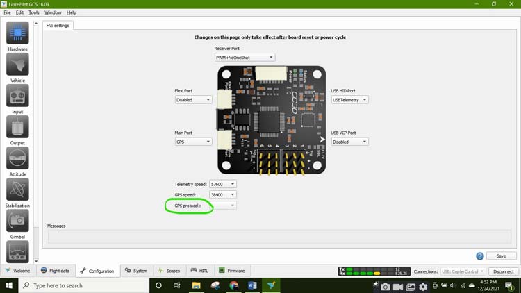
Step-12 Click on the Hardware option on the left-hand side and select the main port as GPS. Select telemetry speed 57600 and GPS speed 38400. But you will not be able to see GPS protocol.
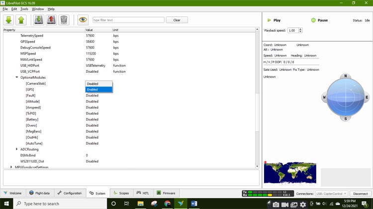
To enable GPS protocol, go to the system option at the bottom menu bar then click the settings option. Now, go to Hw settings then click on the Optional Modules option. Go to the GPS option and enable the GPS.
To upload settings to the CC3D board, click the upside arrow on the top left corner of the window. Remove CC3D connection with PC and plugin again it into PC. Open the GCS software, now you are able to see GPS protocol on it.
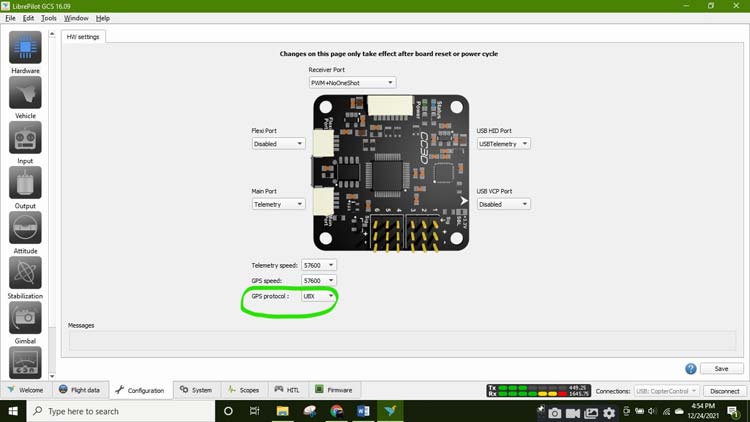
Click on the Save button to save all the settings.
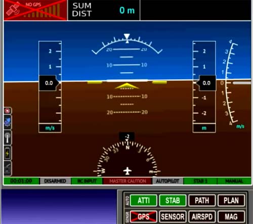
Step-14 Go to the flight data option and now you can see green colored GPS option, which means GPS is working properly. If the GPS option is black colored then it means that GPS is not properly connected with the CC3D board.
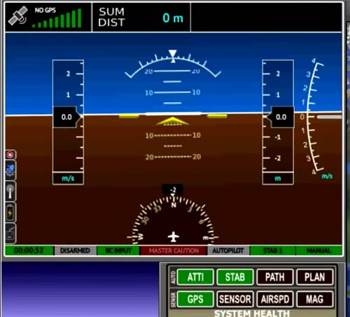
In the below image, you can see a cross sign in GPS, which means GPS is not properly connected.
So, this is how you can interface GPS with the CC3D flight controller. Hope you enjoyed the project and learned something useful. If you have any questions, please leave them in the comment section below or use our forum to start a discussion on this.
