Over the course of a few years, RGB LEDs are getting popular day by day due to its beautiful color, brightness, and enticing lighting effects. That is why It is used in many places as a decorative item, an example can be the home or an office space. Also, we can use the RGB lights in the kitchen and also in a gaming console. They’re also great in a kid’s playroom or bedrooms in terms of mood lighting. Previously, We used the WS2812B NeoPixel LEDs and the ARM Microcontroller to build a Music Spectrum Visualizer, so do check that out if that’s interesting to you.
That is why in this project we are going to use a Neopixel Based RGB LED matrix shield, Arduino, and Blynk application to produce many fascinating animation effects and colors which we will be able to control with the Blynk app. So let’s get started!!!
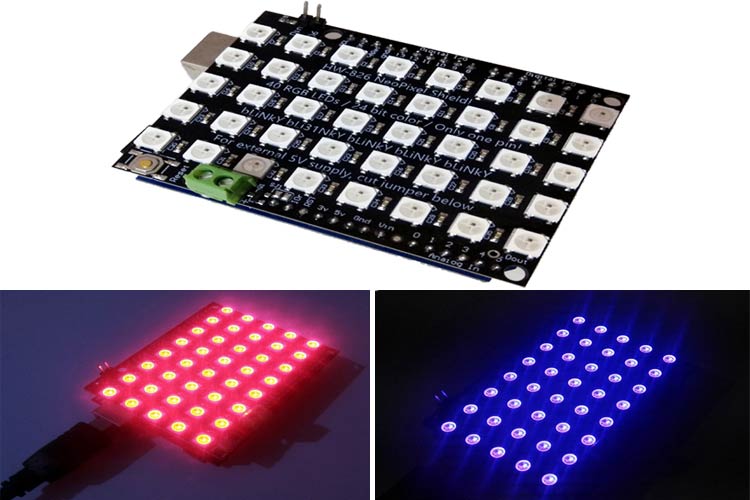
Adafruit 5X8 NeoPixel Shield for Arduino
![]()
The Arduino compatible NeoPixel Shield contains forty individually addressable RGB LEDs each one has the WS2812b driver built-in, which is arranged in a 5×8 matrix to form this NeoPixel Shield. Multiple NeoPixel Shields can also be connected to form a larger Shield if that's a requirement. To control the RGB LEDs, a single Arduino pin is required, so in this tutorial, we have decided to use pin 6 of the Arduino to do so.
In our case, the LEDs are powered from the Arduino’s inbuilt 5V pin, which is sufficient for powering about “a third of the LEDs” at full brightness. If you need to power more LEDs, then you can cut the inbuilt trace and use an external 5v supply to power the shield using the External 5V terminal.
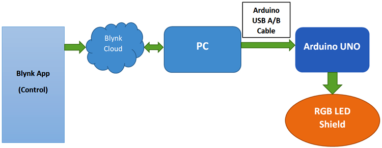
Understanding the Communication Process Between Blynk App and Arduino
The 8*5 RGB LED matrix which is used here is having forty individually addressable RGB LEDs based on WS2812B driver. It has 24-bit color control and 16.8 million colors per pixel. It can be controlled with the “One wire control” methodology. That means we can control the whole LED pixel using a single control pin. While working with the LEDs, I have gone through the datasheet of these LEDs where I find the operating voltage range of the shield is 4 V to 6 V and the current consumption is found out 50 mA per LED at 5 V with red, green, and blue at full brightness. It is having Reverse-voltage protection on the external power pins and a Reset button on the Shield to reset the Arduino. It has also an External Power input pin for LEDs if a sufficient amount of power is not available through internal circuitry.
As shown in the schematic diagram above, we need to download and install the Blynk application on our smartphone where the parameters such as color, brightness can be controlled. After setting up the parameters, if any changes happen to the app, it's to the Blynk cloud where our PC is also connected and ready to receive the updated data. The Arduino Uno is connected to our PC via USB cable with a communication port opened, with this communication port (COM Port), data can be exchanged between the Blynk cloud and Arduino UNO. PC is requesting data from Blynk cloud at constant time intervals and when an updated data is received, it transfers it to Arduino and makes user-defined decisions like controlling the RGB led brightness and Colors. The RGB LED shield is placed on the Arduino LED and connected via a single data pin for communication, by default it is connected via the D6 pin of Arduino. The serial data sent from Arduino UNO are sent to the Neopixel shied which is then reflected on the LED matrix.
Components Required
- Arduino UNO
- 8*5 RGB LED Matrix shield
- USB A/B cable for Arduino UNO
- Laptop/PC
Adafruit RGB LED Shield and Arduino - Hardware Connection
The WS2812B Neopixel LEDs have three pins, one is for data and another two is used for power, but this specific Arduino shield makes the hardware connection very simple, all we have to do is place the Neopixel LED matrix on the top of Arduino UNO. In our case, the LED is powered from the default Arduino 5V Rail. After placing the Neopixel Shield, the setup looks like below:

Configuring up the Blynk Application
Blynk is an application that can run over Android and IOS devices to control any IoT devices and Appliances using our smartphones. First of all, a Graphical User Interface (GUI) needs to be created to control the RGB LED matrix. The application will send all the selected parameters from the GUI to the Blynk Cloud. In the receiver section, we have Arduino connected to the PC via a serial communication cable. Hence, PC requests data from the Blynk cloud, and these data are sent to Arduino for necessary processing. So, let’s get started with the Blynk application setup.
Before the setup, download the Blynk Application from the Google Play store (IOS users can download from App Store). After installation, Sign-up using your email id and Password.
Creating a New Project:
After successful installation, open the application, and there we will get a screen with an option “New Project”. Click on it and it will pop up a new screen, where we need to set the parameters like Project name, Board, and connection type. In our project, select the device as “Arduino UNO” and connection type as “USB” and click on “Create”.
After the successful creation of the Project, we will get an Authenticate ID in our registered mail. Save the Authenticate ID for future reference.

Creating the Graphic User Interface (GUI):
Open the project in Blynk, click on the “+” sign where we will get the widgets which we can use in our project. In our case, we need an RGB Color Picker which is listed as “zeRGBa” as shown below.

Setting the Widgets:
After dragging the widgets to our project, now we have to set its parameters which are used to send the color RGB values to Arduino UNO.
Click on ZeRGBa, then we will get a screen named ZeRGBa setting. Then set the Output option to “Merge” and set the pin to “V2” which is shown in the image below.

Arduino Code Controlling Adafruit WS2812B RGB LED Shield
After completion of the hardware connection, the code needs to be uploaded to Arduino. The step by step explanation of the code is shown below.
First, include all the required libraries. Open Arduino IDE, then go to the tab Sketch and click on the option Include Library-> Manage Libraries. Then search for Blynk in the search box and then download and install the Blynk package for Arduino UNO.
Here “Adafruit_NeoPixel.h” library is used to control the RGB LED Matrix. To include it, You can download the Adafruit_NeoPixel library from the given link. Once you got that, you can include it with the Include ZIP Library option.
#define BLYNK_PRINT DebugSerial
#include <Adafruit_NeoPixel.h>
#include <SoftwareSerial.h>
Then we define the number of LEDs, which is required for our LED matrix, also we define the pin-number which is used to control the LED parameters.
#define PIN 6
#define NUM_PIXELS 40
Then, we need to put our blink authentication ID in an auth[] array, which we have saved earlier.
char auth[] = "HoLYSq-SGJAafQUQXXXXXXXX";
Here software serial pins are used as debug console. So, the Arduino pins are defined as debug serial below.
#include <SoftwareSerial.h>
SoftwareSerial DebugSerial(2, 3);
Inside setup, Serial communication is initialized using function Serial.begin, blynk is connected using Blynk.begin and using pixels.begin(), the LED Matrix is initialized.
void setup()
{
  DebugSerial.begin(9600);
  pixels.begin();
  Serial.begin(9600);
  Blynk.begin(Serial, auth);
}
Inside the loop (), we have used Blynk.run (), which checks for incoming commands from blynk GUI and executes the operations accordingly.
void loop()
{
  Blynk.run();
}
In the final stage, the parameters which were sent from the Blynk application need to be received and processed. In this case, the parameters were allotted to a virtual pin “V2” as discussed earlier in the setup section. BLYNK_WRITE function is an inbuilt function that gets called whenever the associated virtual pin’s state/value changes. we can run code inside this function just like any other Arduino function.
Here BLYNK_WRITE function is written to check for incoming data at virtual pin V2. As shown in the Blink setup section, the color pixel data were merged and assigned to the V2 pin. So we also have to de-merge again after decoding. Because to control the LED pixel matrix, we need all 3 individual color pixel data such as Red, green, and Blue. As shown in the code below, three indexes of the matrix were read like param[0].asInt() to get the value of Red color. Similarly, all the other two values were received and stored in 3 individual variables. Then these values are assigned to the Pixel matrix using pixels.setPixelColor function as shown in the code below.
Here, pixels.setBrightness() function is used to control the brightness and pixels.show() function is used to display the set colour in the Matrix.
BLYNK_WRITE(V2)
{
int r = param[0].asInt();
int g = param[1].asInt();
int b = param[2].asInt();
pixels.clear();
pixels.setBrightness(20);
for (int i=0; i<=NUM_PIXELS;i++)
{
pixels.setPixelColor(i, pixels.Color(r, g, b));
}
pixels.show();
}
Uploading the Code to Arduino Board
First, we need to select the PORT of the Arduino inside the Arduino IDE, then we need to upload the code into Arduino UNO. After a successful upload, note down the Port-Number which will be used for our serial communication setup.
After this, find the script folder of the Blynk library on your PC. It gets installed when you install the library, mine was in,
“C:\Users\PC_Name\Documents\Arduino\libraries\Blynk\scripts”
In the script folder, there should a file named “blynk-ser.bat” which is a batch file used for serial communication which we need to edit with notepad. Open the file with notepad and change the Port number to your Arduino Port number which you have noted in the last step.
After editing, save the file and run the batch file by double-clicking on it. Then, you must be seeing a window like shown below:

Note: If you are not able to see this window shown above and it is prompted to reconnect, then it might be due to the error in connection of PC with the Arduino shield. In that case, check your Arduino connection with the PC. After that, check if the COM port number is showing in the Arduino IDE or not. If it is showing the valid COM port, then it is ready to proceed. You should run the batch file again.
Final Demonstration:
Now, it’s time for testing the circuit and its functionality. Open the Blynk application and open the GUI and click on the Play button. After that, you can select any of your desired colors to be reflected on the LED Matrix. As shown below, in my case I have selected the Red and Blue color, it is being displayed on the Matrix.

Similarly, you can also try to make different animations using these LED matrices by customizing the coding a bit.
#define BLYNK_PRINT DebugSerial
#include <Adafruit_NeoPixel.h>
#include <SoftwareSerial.h>
SoftwareSerial DebugSerial(2, 3);
#include <BlynkSimpleStream.h>
char auth[] = "-54csCxRMCSyHxxxxxxxxx";
#define PIN 6
#define NUM_PIXELS 40
Adafruit_NeoPixel pixels(NUM_PIXELS, PIN, NEO_GRB + NEO_KHZ800);
void setup()
{
  DebugSerial.begin(9600);
  pixels.begin();
  Serial.begin(9600);
  Blynk.begin(Serial, auth);
}
void loop()
{
  Blynk.run();
}
BLYNK_WRITE(V2)
{
int r = param[0].asInt();
int g = param[1].asInt();
int b = param[2].asInt();
pixels.clear();
pixels.setBrightness(20);
for (int i=0; i<=NUM_PIXELS;i++)
{
pixels.setPixelColor(i, pixels.Color(r, g, b));
}
pixels.show();
}


