In ARDUINO we have 20 I/O pins, so we can program 20 pins of UNO to be used as either input or output. Although there are more pins on ATMEGA328P controller than on UNO, this is because while designing the board some pins are defaulted.
Now for some applications we need more than 30 pins, say if we want to design a 5x5x5 LED CUBE, so for this we need 5x5+5=30pins. For such cases we use serial to parallel converter chips or shift register. A shift register chip takes data from UNO board serially and gives output in 8 bit parallel configuration.
Components Required
Hardware: Arduino uno board, connecting pins, 220Ω resistor, LED (eight pieces), 74HC595 IC, bread board.
Sofware: Arduino nightly
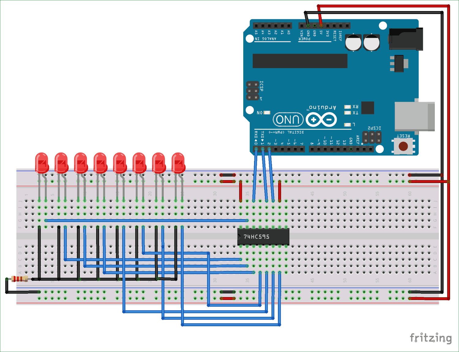
Circuit Diagram and Working Explanation
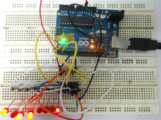
Here we are going to send data in eight bit size through a single channel to shift register. The shift register takes the data serially and stores that data in its memory. Once the data is sent by the controller, we are going to send a command to shift register to show the data at the output, with this command the shift register puts out data parallel.
This output is shown by eight LED connected at output.
For connecting the shift register to Arduino UNO we need to do two things:
|
First we need to set any three pins of UNO as output. Then we need to connect digital pin, clock pin and latch pin to these three output pins. After that we need to tell the UNO which pin of chip is connected to UNO board pins. This is done by simple writing in command “shiftOut(dataPin, clockPin, data);”. The data here can be in binary or decimal or hexadecimal. The eight bit information which needs to be sent is written in place of “data”.
The data sent is done as:
Disable latch, this tells chip to not to show output for now.
For eight times we will send data with clock serially, so clock high low-data-clock low- and so on.
Enable latch, this tells chip to show eight bit data.
Working of ARDUINO with SHIFT REGISTER is explained step by step in C code given below:
// The setup function runs once when you press reset or power the board
volatile int i=0;
void setup()
{
pinMode(2, OUTPUT); // sets the pin2 as output
pinMode(1, OUTPUT); // sets the pin1 as output
pinMode(0, OUTPUT); // sets the pin0 as output
}
void loop()
{
for (int i=0;i<255;i++) //if binary count is less than 255
{
digitalWrite(2,HIGH);
shiftOut(0,1,2,i); //send eight bit data serially for each time there is a increment
digitalWrite(2,LOW);
delay(500); //wait for half a second
}
}


