

Most of us would be familiar with the 16×2 Dot matrix LCD display that is used in most of the projects to display some information to the user. However, these LCD displays have a lot of limitations in what they can do. In this tutorial, we are going to learn about OLED displays and how to use them with Arduino. There are many types of OLED displays available in the market and there are lots of ways to get them working. In this tutorial, we will discuss its classifications and also which will be best suited for your project.
OLED Display - Overview
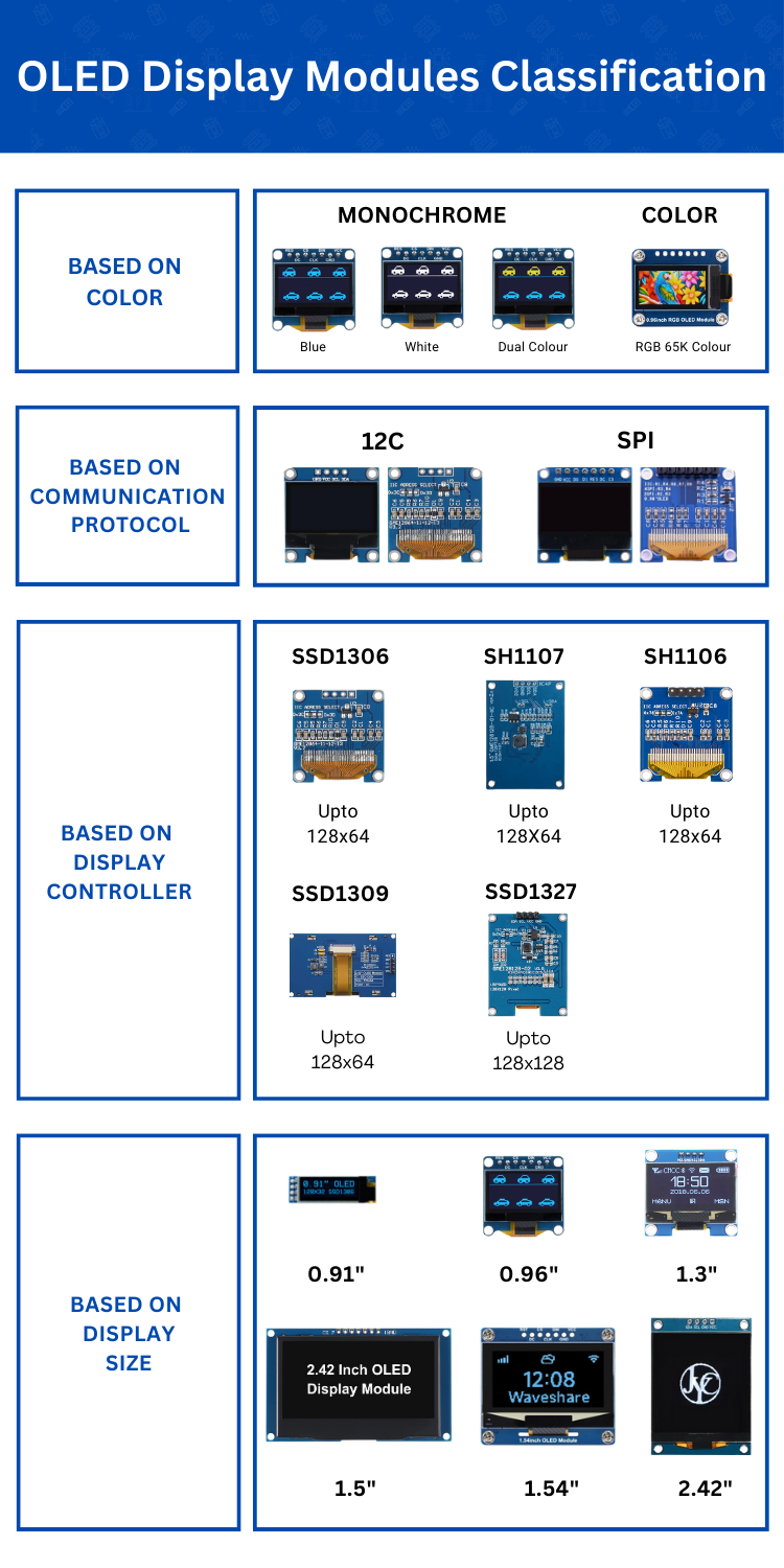
OLED displays are available in different sizes, different resolutions, different communication protocols and with different types of display controllers. So, let's look at the different types of OLED displays. The image below shows the categorization in OLED display modules based on the above parameters.
I2C OLED Display Module Pinout
This OLED module leverages I2C for communication with the microcontroller. You can also find similar displays with either I2C or SPI interface or even with both in the same PCB. The module we are using has 4 pins in total. The pinout of an I2C OLED Display Module is shown below-
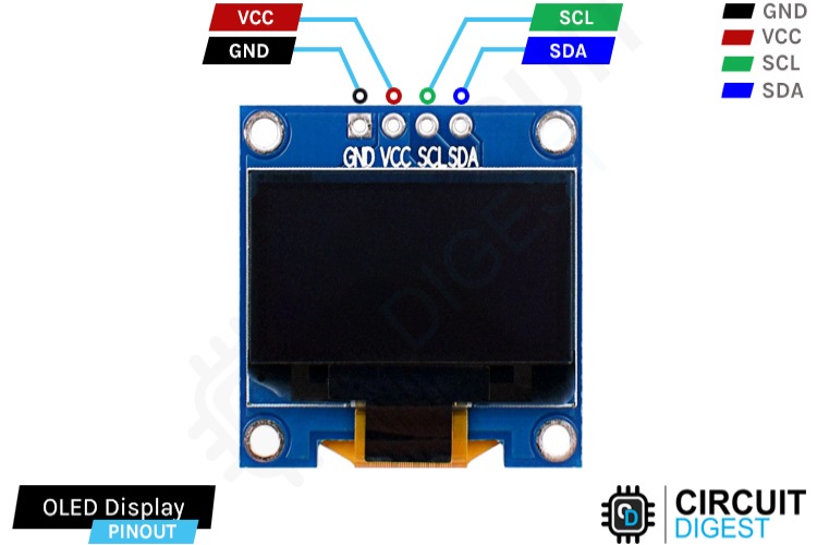
GND Ground connection for the module. Connect to the GND pin of the Arduino.
VCC Provides power for the module. Connect to the 5V pin of the Arduino.
SCL Serial Clock pin. Used for providing clock pulse for I2C Communication.
SDA Serial Data pin. Used for transferring Data through I2C communication.
Keep in mind that some display module in the market comes with the pin positions swapped. So always check the pin labelling on the silkscreen before making the connections. Some modules come with a 3.3V regulator on boards and some don’t. If your module doesn’t have this regulator onboard, use the module only with 3.3V devices. Otherwise, you may end up damaging them. If it has a regulator with the marking 662K you can use it with 5V devices.
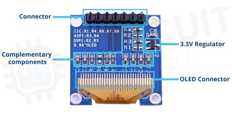
I2C OLED Module Parts
The below image shows the components on the I2C OLED display module PCB.
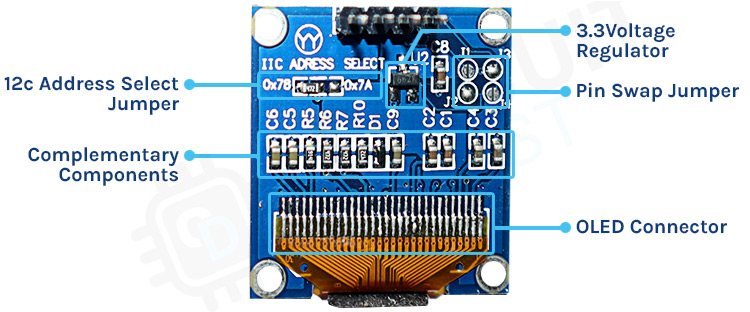
The XC6206P332 Voltage regulator steps down the input voltage to 3.3V. The inclusion of this voltage regulator allows us to interface the OLED module to even 5.5V microcontrollers or circuits. We can also set the OLED module I2C address by changing the position of the address select resistor. The I2C default address is 0x78 (0x3C in 7-bit) and can be changed to 0x7A (0x3D in 7-bit).
Circuit Diagram for an I2C OLED Module
The Schematic diagram for the OLED module is given below. The circuit consists of bare minimum components.

As you can see the board contains very few components. Most of them are complimentary resistors and capacitors which are necessary for the SSD1306 display controller in the OLED panel. Other components include the 3.3V voltage regulator (XC6206P332), pullup resistors for the I2C line, and the address select resistor. You can also find display modules with both SPI and I2C connections. In those modules, the BS1 pin will be connected to VCC for I2C and to ground for SPI. similarly, when using SPI, the address select pin will be used as the data/command pin aka D/C pin, the D2 pin will be disconnected from the D1 pin, CS pin will be removed from the GND and brought out to the external connector, and additional pull-up resistors will be added to the D/C and CS pins.
SPI OLED Display Module Pinout
This OLED module uses SPI for communication with the microcontroller. SPI is much faster than I2C, and thus we can get a much better frame rate by using the SPI bus. The module we are using has 7 pins in total. The pinout of an SPI OLED Display Module is shown below-
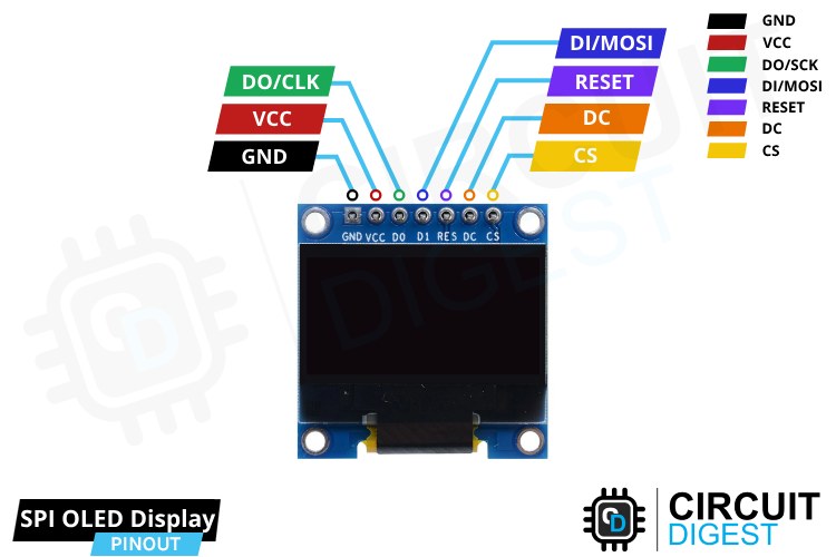
GND Ground connection for the module. Connect to the GND pin of the Arduino.
VCC Provides power for the module. Connect to the 5V pin of the Arduino.
D0/CLK SPI Clock pin. Used for providing clock pulse for SPI Communication.
D1/MOSI Serial Data In pin. Used for sending data to the display.
RESET Reset pin to reset the internal buffer of the display.
DC Data/ Command Pin. Used to control the type of data sent to the display.
CS Chip select pin. Used as the chip select input for the display controller.
SPI OLED Module Parts
The below image shows the components on an SPI OLED display module.
Here you can see that we can use this module with either I2C, 3-wire SPI or 4-wire SPI interfaces. To choose the desired protocol all we have to do is populate the or remove the corresponding resistors mentioned on the PCB itself.
Circuit Diagram for an SPI OLED Module
The Schematic diagram for the OLED module is given below. The circuit consists of bare minimum components.
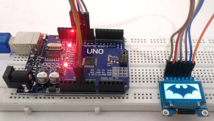
I2C OLED Module Interfacing Connection Diagram
The following image shows how to connect an I2C OLED module with the Arduino board.
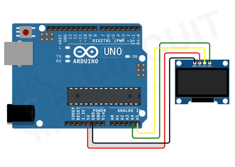
The connections are very simple, connect the GND pin to the GND pin of the Arduino and VCC to the 5V pin. The SCL is connected to the A5 and the SDA is connected to the A4 pin of the Arduino.
SPI OLED Module Interfacing Connection Diagram
The following image shows how to connect an SPI OLED module with the Arduino board.
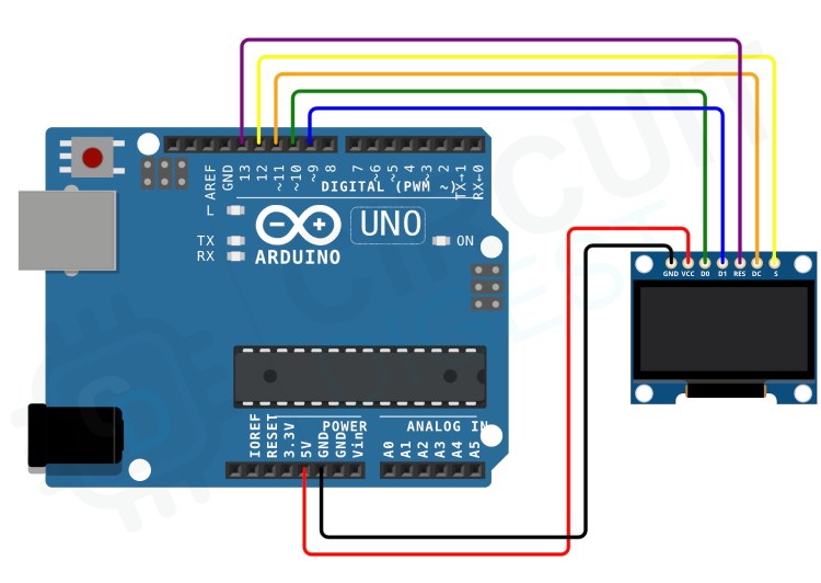
Compared to the I2C, the SPI interface needs a few more pins. As usual, the VCC and GND pins are connected to the 5V and GND pins of the Arduino. For the SPI the D0, D1, RES, DC and CS pins are connected to digital pins 10, 9, 13, 11 and 12 respectively.
You can also check out this Wokwi Arduino OLED Display Simulation if you wish to see how your Arduino code will work on your OLED display without actually using the hardware. This will come very handy when you are creating new GUI or animation on your OLED display.
Arduino Code with Basic Text and Graphics Functions
Once the connections are ready you can start programming the Arduino. Whether we use I2C or SPI interface for the OLED display, the code is almost the same. Let's start with installing the necessary libraries. For this tutorial, we will need to install two Arduino libraries, Adafruit SSD1306 and Adafruit GFX libraries. The easiest to way to install them is to use the Arduino IDE library manager, just search for these libraries and install them. Once the libraries are successfully installed, copy and paste the following code to the Arduino IDE. Make the changes depending on whether you are using I2C or SPI interface and then compile and upload it to the Arduino.
Now let's look at the code. As usual at the start, we need to include all the necessary libraries and we must declare any global variable. Later we included the SPI.h library for SPI interfacing and wire.h library I2C interfacing. Depending on the module and interfacing you only need to add either of them. Then we have defined the screen resolution as SCREEN_WIDTH and SCREEN_HIGHT. For I2C interfacing, since we don’t use the reset pin, we declared its value to be -1 so that the library won’t misbehave. Next, we have changed the OLED address to 0x3C. Change this according to your display module. If you are not sure you can use the I2C scanner example to identify the module’s I2C address. Then we created an instance called display to use all along with the program. We will use this instance to access all the Adafruit GFX library features.
#include <SPI.h>
#include <Wire.h>
#include <Adafruit_GFX.h>
#include <Adafruit_SSD1306.h>

#define SCREEN_WIDTH 128 // OLED display width, in pixels
#define SCREEN_HEIGHT 64 // OLED display height, in pixels

// Declaration for SSD1306 display connected using I2C
#define OLED_RESET     -1 // Reset pin # (or -1 if sharing Arduino reset pin)
#define SCREEN_ADDRESS 0x3C
Adafruit_SSD1306 display(SCREEN_WIDTH, SCREEN_HEIGHT, &Wire, OLED_RESET);
If you are using the SPI instead of I2C Just comment out or remove the above said definitions and the display instance. Instead, remove the command tag from the SPI pin definitions and the display instance.
// Declaration for SSD1306 display connected using software SPI:
//#define OLED_MOSI   9
//#define OLED_CLK   10
//#define OLED_DC    11
//#define OLED_CS    12
//#define OLED_RESET 13
//Adafruit_SSD1306 display(SCREEN_WIDTH, SCREEN_HEIGHT, OLED_MOSI, OLED_CLK, OLED_DC, OLED_RESET, OLED_CS);
In the setup function, first, we have initialized the serial port, which can be used for debugging if needed. Later we called the display.begin function to initialize the display. As you can see, the function call uses two arguments, of which one is the I2C address of the display. For SPI interfacing you don’t need the second argument, so just remove that if you are using SPI. Then we cleared the display buffer with the help clearDisplay function. This will clear any data that’s on the display if the display is not reset previously. We will be using this function all along the code to clear anything on the display. Now let’s look at each section and what’s their functions.
void setup()
{
 Serial.begin(9600);
  // initialize the OLED object
 if(!display.begin(SSD1306_SWITCHCAPVCC, SCREEN_ADDRESS)) {
   Serial.println(F("SSD1306 allocation failed"));
   for(;;); // Don't proceed, loop forever
 }

 // Uncomment this if you are using SPI
 //if(!display.begin(SSD1306_SWITCHCAPVCC)) {
 //  Serial.println(F("SSD1306 allocation failed"));
 //  for(;;); // Don't proceed, loop forever
 //}

// Clear the buffer.
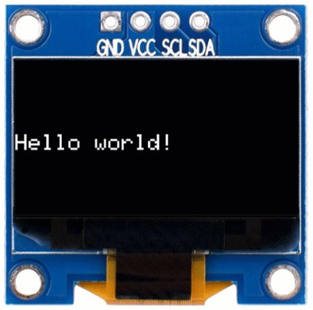
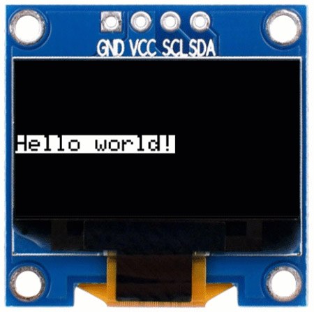
Displaying Text
 display.clearDisplay();
 // Display Text
 display.setTextSize(1);
 display.setTextColor(WHITE);
 display.setCursor(0, 28);
 display.println("Hello world!");
 display.display();
 delay(2000);
 display.clearDisplay();
The above section will print the word Hello world! to the OLED display. Before printing the text, we have called a few other functions. The display.setTextSize(size) will set the text size, the display.setTextColor(colour) will set the text colour to white, and finally the display.setCursor(x,y) sets the cursor to the position that corresponds to the x, y coordinates we have provided. Once the print function is called we will call the display.display() which will tell the display controller to display the buffer content on the screen. The display won’t show what we have transferred to the buffer unless this function is called.
Displaying Inverted Text
 // Display Inverted Text
 display.setTextColor(BLACK, WHITE); // 'inverted' text
 display.setCursor(0, 28);
 display.println("Hello world!");
 display.display();
 delay(2000);
 display.clearDisplay();
In this section, we have used the setTextcolor function to declare the text colour as well as the text background colour. This will print the text in black colour with a white text background.
Increase Text Size
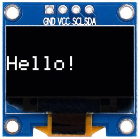
 // Changing Font Size
 display.setTextColor(WHITE);
 display.setCursor(0, 24);
 display.setTextSize(2);
 display.println("Hello!");
 display.display();
 delay(2000);
 display.clearDisplay();) {
}
This section demonstrates how to change the text size. You can see that the text size doubled when we increased the value we passed to the setTextSize function.
Displaying Numbers
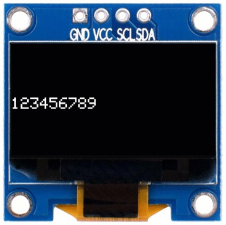
 // Display Numbers
 display.setTextSize(1);
 display.setCursor(0, 28);
 display.println(123456789);
 display.display();
 delay(2000);
 display.clearDisplay();
This is also similar to displaying a text. You can simply use the print or println function to print the value to the display.
Displaying a Base Encoded Number
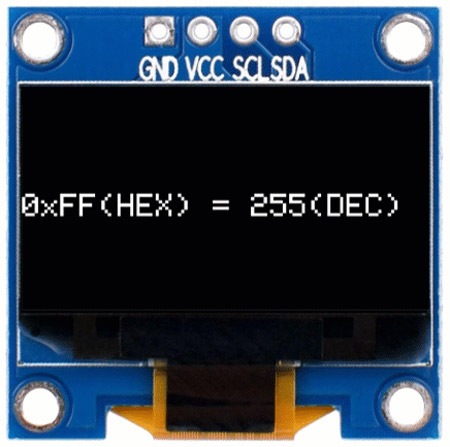
 // Specifying Base For Numbers
 display.setCursor(0, 28);
 display.print("0x"); display.print(0xFF, HEX);
 display.print("(HEX) = ");
 display.print(0xFF, DEC);
 display.println("(DEC)");
 display.display();
 delay(2000);
 display.clearDisplay();
This will help you print any numbers as it is. For example, if you want to print a Hex value, you can do that by simply mentioning the base within the print or println function. The format is as follows print(value, base).
Displaying Glyph or ASCII Characters
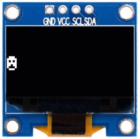
 // Display ASCII Characters
 display.setCursor(0, 24);
 display.setTextSize(2);
 display.write(1);
 display.display();
 delay(2000);
 display.clearDisplay();
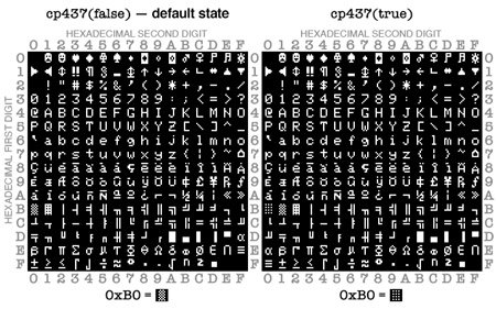
The font files not only contain alphanumeric characters but also small symbols or graphical characters. To display them we can use the write function. You can display any ASCII character in your font file by just writing the ASCII code for that specific character. In the example, we have printed the smiley face which has the ASCII code 0x01. Below is the ASCII character table for the default font used with the Adafruit GFX library. You can use your own font files and they may contain different Glyphs with different ASCII codes.
Scrolling
 // Scroll full screen
 display.setCursor(0, 0);
 display.setTextSize(1);
 display.println("Full");
 display.println("screen");
 display.println("scrolling!");
 display.display();
 display.startscrollright(0x00, 0x07);
 delay(4500);
 display.stopscroll();
 delay(1000);
 display.startscrollleft(0x00, 0x07);
 delay(4500);
 display.stopscroll();
 delay(1000);
 display.startscrolldiagright(0x00, 0x07);
 delay(4500);
 display.startscrolldiagleft(0x00, 0x07);
 delay(4500);
 display.stopscroll();
 display.clearDisplay();
Just like in the character LCDs we can also scroll text or even the entire screen with the Adafruit GFX library. The startscrollright and startscrollleft functions will scroll the display to the right or left respectively. The values within the functions are the start and end page numbers. The current values in the code will scroll the entire display i.e. the whole 8 pages.
Drawing Rectangles
//draw rectangle
display.setTextSize(1);
display.setTextColor(WHITE);
display.setCursor(0, 0);
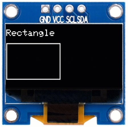
display.println("Rectangle");
display.drawRect(0, 15, 60, 40, WHITE);
display.display();
delay(2000);
display.clearDisplay();
The function is simple. You will need to specify the coordinate of the top left corner and the width, height, and color of the rectangle as follows drawRect(x, y, width, height, colour).
Drawing Filled Rectangles
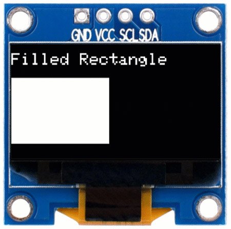
 //draw filled rectangle
 display.setCursor(0, 0);
 display.println("Filled Rectangle");
 display.fillRect(0, 15, 60, 40, WHITE);
 display.display();
 delay(2000);
 display.clearDisplay();
The function is similar to the drawRect function, the only difference is that it will fill up the rectangle. You will need to specify the coordinate of the top left corner and the width, height, and color of the rectangle as follows fillRect(x, y, width, height, colour).
Drawing Rectangles with Rounded Corners
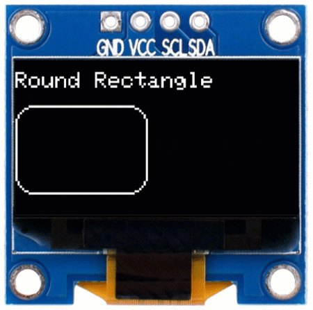
 //draw rectangle with rounded corners
 display.setCursor(0, 0);
 display.println("Round Rectangle");
 display.drawRoundRect(0, 15, 60, 40, 8, WHITE);
 display.display();
 delay(2000);
 display.clearDisplay();
The function is also similar to the drawRect function. You will need to specify the coordinate of the top left corner and the width, height, radius of the corner, and color of the rectangle as follows drawRoundRect (x, y, width, height, radius, colour).
Drawing Filled Rectangles with Rounded Corners
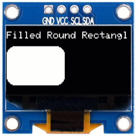
 //draw filled rectangle with rounded corners
 display.setCursor(0, 0);
 display.println("Filled Round Rectangle");
 display.fillRoundRect(0, 15, 60, 40, 8, WHITE);
 display.display();
 delay(2000);
 display.clearDisplay();
The function is also similar to the drawRoundRect function, the only difference is that it will fill up the rounded rectangle. You will need to specify the coordinate of the top left corner and the width, height, radius of the corner, and color of the rectangle as follows fillRoundRect (x, y, width, height, radius, colour).
Drawing Circle
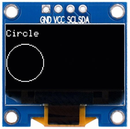
//draw circle
 display.setCursor(0, 0);
 display.println("Circle");
 display.drawCircle(20, 35, 20, WHITE);
 display.display();
 delay(2000);
 display.clearDisplay();
To draw a circle we can use the drawCircle function. This function requires three parameters – the x and y coordinates for the centre point and the radius of the circle. The function format is drawCircle(x, y, Radius).
Drawing Filled Circle
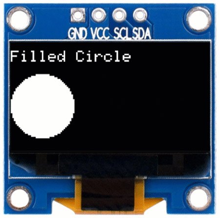
 //draw filled circle
 display.setCursor(0, 0);
 display.println("Filled Circle");
 display.fillCircle(20, 35, 20, WHITE);
 display.display();
 delay(2000);
 display.clearDisplay();
To draw a filled circle, we can use the fillCircle function. This function requires three parameters – the x and y coordinates for the centre point and the radius of the circle. The function format is fillCircle(x, y, Radius).
Drawing Triangle
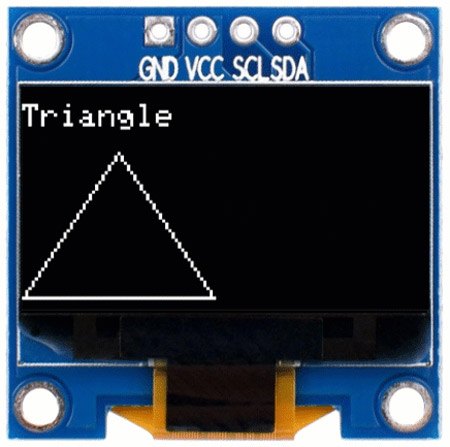
//draw triangle
 display.setCursor(0, 0);
 display.println("Triangle");
 display.drawTriangle(30, 15, 0, 60, 60, 60, WHITE);
 display.display();
 delay(2000);
 display.clearDisplay();
To draw a triangle, the drawTriangle function requires a full set of seven parameters: the X, and Y coordinates for three corner points defining the triangle, followed by the colour. The format is drawTriangle(x1, y1, x2, y2, x3, y3, Colour).
Drawing Filled Triangle
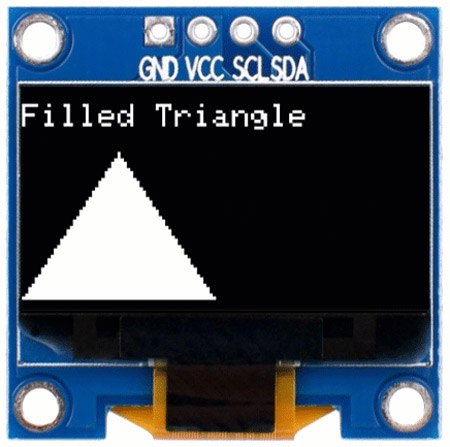
 //draw filled triangle
 display.setCursor(0, 0);
 display.println("Filled Triangle");
 display.fillTriangle(30, 15, 0, 60, 60, 60, WHITE);
 display.display();
 delay(2000);
 display.clearDisplay();
}
Similar to the drawTriangle function, the fillTriangle function also requires a full set of seven parameters: the X, and Y coordinates for three corner points defining the triangle, followed by the colour. The format is fillTriangle(x1, y1, x2, y2, x3, y3, Colour).
Displaying Image on OLED Display
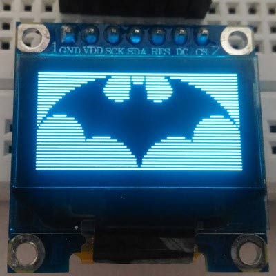
To display an image, first, you need to make sure its resolution is within the OLED size. For our example, we will need to resize any image that we are going to use to a resolution of 128x64 pixels. After that, we will need to convert this to a hex data array so that we can store this image in the code and can recall it whenever needed. There are multiple ways to do all these and I’m going to show you the easiest of them. For that go to the Image2cpp website and upload your picture.
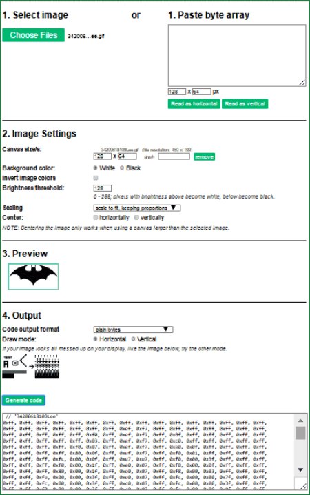
Set the canvas type size to 128 x 64. You can resize the image using the scaling option. Change all other settings until you are satisfied with the preview. Once you are done with all the changes select Arduino code as Code output format and click on the generate code button. The corresponding array containing image data will be displayed below. Copy this code and paste it to the global variable section of the code. Once done use the array name with the drawBitmap(x, y, array_name, Width, Hieght, Colour) function. Here is an example, in which we have displayed the bat symbol using this function.
Commonly Asked Questions about using OLED Display with Arduino
Q. What is an OLED display module?
OLED is an Organic Light Emitting Diode. OLED Display is a self-light-emitting technology composed of a thin, multi-layered organic film placed between an anode and cathode. In contrast to LCD technology, OLED does not require a backlight.
Q. What is the display controller used in these OLED modules?
SSD1306, SH1106, SSD1327, SH1107 and SSD1309 are the most commonly used display controllers in the small OLED modules.
Q. What type of protocol do OLED modules use?
The OLED modules support I2C or SPI protocols.
Q. What are the commonly available OLED display sizes and resolutions?
Even though OLED displays are available in different sizes and resolutions, the most commonly used ones are 0.96” and 1.3” modules with 128x64 Dpi resolution. Modules with a resolution of 128x32 are also common in the DIY community.
Arduino OLED module not working?
If your OLED module is not working with the Arduino, here are some common troubleshooting tips you can do.
Check Connections: Ensure all connections between the OLED module and the Arduino board are secure and properly made. A loose or incorrectly connected wire could cause issues.
Power Supply: Verify that the OLED module is receiving power from the Arduino board or an external power supply if required. Check the power supply voltage to ensure it matches the specifications of the OLED module.
Library and Code: Make sure you have installed the necessary libraries for the OLED module and that your code is correctly written. Double-check the code for any errors or missing commands that could prevent the OLED from displaying properly.
Use Proper Communication Protocol: Some modules come with either the I2C or SPI connection, while some come with both. When using the OLED module make sure to connect and use it with the connections it comes with. And for modules with both I2C and SPI pins configure the module to use the appropriate protocol by using the jumpers on the PCB.
I2C address: If you are using an I2C OLED module, use an I2C scanner program to scan for the OLED module’s I2C address. Use this address on your code to communicate with the module.
Test with Example Code: Use the example code provided by the manufacturer or community to test the OLED module. If it works with the example code, then the issue might be with your own code.
Check Display Settings: Some OLED modules may have settings that need to be configured before they can display properly. Refer to the module's datasheet or documentation to ensure the settings are correctly configured.
Check for Hardware Issues: Inspect the OLED module for any visible damage or defects. Sometimes, a faulty OLED screen or a damaged connection can cause display issues.
Test with Another Arduino Board: If possible, try connecting the OLED module to another Arduino board to see if the issue persists. This can help determine if the problem is with the Arduino board or the OLED module itself.
Here’s the GitHub repo where you can find the complete code and the circuit diagrams that we have used in this tutorial.


#include <SPI.h>
#include <Wire.h>
#include <Adafruit_GFX.h>
#include <Adafruit_SSD1306.h>
#define SCREEN_WIDTH 128 // OLED display width, in pixels
#define SCREEN_HEIGHT 64 // OLED display height, in pixels
// Declaration for SSD1306 display connected using I2C
#define OLED_RESET -1 // Reset pin # (or -1 if sharing Arduino reset pin)
#define SCREEN_ADDRESS 0x3C
Adafruit_SSD1306 display(SCREEN_WIDTH, SCREEN_HEIGHT, &Wire, OLED_RESET);
// Declaration for SSD1306 display connected using software SPI:
//#define OLED_MOSI 9
//#define OLED_CLK 10
//#define OLED_DC 11
//#define OLED_CS 12
//#define OLED_RESET 13
//Adafruit_SSD1306 display(SCREEN_WIDTH, SCREEN_HEIGHT, OLED_MOSI, OLED_CLK, OLED_DC, OLED_RESET, OLED_CS);
void setup()
{
Serial.begin(9600);
// initialize the OLED object
if(!display.begin(SSD1306_SWITCHCAPVCC, SCREEN_ADDRESS)) {
Serial.println(F("SSD1306 allocation failed"));
for(;;); // Don't proceed, loop forever
}
// Uncomment this if you are using SPI
//if(!display.begin(SSD1306_SWITCHCAPVCC)) {
// Serial.println(F("SSD1306 allocation failed"));
// for(;;); // Don't proceed, loop forever
//}
// Clear the buffer.
display.clearDisplay();
// Display Text
display.setTextSize(1);
display.setTextColor(WHITE);
display.setCursor(0, 28);
display.println("Hello world!");
display.display();
delay(2000);
display.clearDisplay();
// Display Inverted Text
display.setTextColor(BLACK, WHITE); // 'inverted' text
display.setCursor(0, 28);
display.println("Hello world!");
display.display();
delay(2000);
display.clearDisplay();
// Changing Font Size
display.setTextColor(WHITE);
display.setCursor(0, 24);
display.setTextSize(2);
display.println("Hello!");
display.display();
delay(2000);
display.clearDisplay();) {
}
// Display Numbers
display.setTextSize(1);
display.setCursor(0, 28);
display.println(123456789);
display.display();
delay(2000);
display.clearDisplay();
// Specifying Base For Numbers
display.setCursor(0, 28);
display.print("0x"); display.print(0xFF, HEX);
display.print("(HEX) = ");
display.print(0xFF, DEC);
display.println("(DEC)");
display.display();
delay(2000);
display.clearDisplay();
// Display ASCII Characters
display.setCursor(0, 24);
display.setTextSize(2);
display.write(1);
display.display();
delay(2000);
display.clearDisplay();
// Scroll full screen
display.setCursor(0, 0);
display.setTextSize(1);
display.println("Full");
display.println("screen");
display.println("scrolling!");
display.display();
display.startscrollright(0x00, 0x07);
delay(4500);
display.stopscroll();
delay(1000);
display.startscrollleft(0x00, 0x07);
delay(4500);
display.stopscroll();
delay(1000);
display.startscrolldiagright(0x00, 0x07);
delay(4500);
display.startscrolldiagleft(0x00, 0x07);
delay(4500);
display.stopscroll();
display.clearDisplay();
//draw rectangle
display.setTextSize(1);
display.setTextColor(WHITE);
display.setCursor(0, 0);
display.println("Rectangle");
display.drawRect(0, 15, 60, 40, WHITE);
display.display();
delay(2000);
display.clearDisplay();
//draw filled rectangle
display.setCursor(0, 0);
display.println("Filled Rectangle");
display.fillRect(0, 15, 60, 40, WHITE);
display.display();
delay(2000);
display.clearDisplay();
//draw rectangle with rounded corners
display.setCursor(0, 0);
display.println("Round Rectangle");
display.drawRoundRect(0, 15, 60, 40, 8, WHITE);
display.display();
delay(2000);
display.clearDisplay();
//draw circle
display.setCursor(0, 0);
display.println("Circle");
display.drawCircle(20, 35, 20, WHITE);
display.display();
delay(2000);
display.clearDisplay();
//draw filled circle
display.setCursor(0, 0);
display.println("Filled Circle");
display.fillCircle(20, 35, 20, WHITE);
display.display();
delay(2000);
display.clearDisplay();
//draw triangle
display.setCursor(0, 0);
display.println("Triangle");
display.drawTriangle(30, 15, 0, 60, 60, 60, WHITE);
display.display();
delay(2000);
display.clearDisplay();
//draw filled triangle
display.setCursor(0, 0);
display.println("Filled Triangle");
display.fillTriangle(30, 15, 0, 60, 60, 60, WHITE);
display.display();
delay(2000);
display.clearDisplay();
}
Comments
Sorry cant help with SSD1331
Sorry patik, I haven't tried a SDD1331 OLED module yet. So can help you with this for now. But I sure the basics will remain the same.
Read data of OLED
Sir, how to read data from OLED for eg if I display eagle using keypad on OLED then how I can read that data from OLED??
Yes it will work, there are
Yes it will work, there are many types of OLED based in size and colour values. You should read this to understand more
https://circuitdigest.com/microcontroller-projects/arduino-ssd1306-oled-display

Hello,
As I have gone through the example which you gave in your blog and it found really helpful to me.
but I am using SSD1331 OLED display and its work on SPI Protocol.
Some of the function may be not supported to SSD1331 OLED.
Please give me a suggestion which modification needed?
Regards,
Pratik