

XOR or EX-OR gate is a digital logic gate, designed for arithmetic and logical operations, Every electronic student must have studied this gate is his/her career. This gate is mainly used in applications where there is a need for mathematical calculations. So in calculators, computers and many digital applications use this gate.
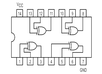
Here we are going to use 74LS86 IC for demonstration, this chip has 4 EX-OR gates in it. These four gate are connected internally as shown in below figure.
Components Required
- Power supply (5v)
- 1K, 220Ω resistor
- 74LS86 QUAD EX-OR GATE IC
- 1 LED
- Buttons
- 100nF capacitor
- Breadboard and Connecting wires
Circuit Diagram and Working Explanation
The truth table of XOR gate is show below:
| IN | OUT | |
| A | B | Z |
| L | L | L |
| L | H | H |
| H | L | H |
| H | H | L |
So as shown in truth table the output of each gate in the chip should be high when any one of two inputs in corresponding gate is high. In an EX-OR gate the output will be low if both inputs are either high or LOW.
In this XOR gate circuit we are going to pull down both input of a gate to ground through a 1KΩ resistor. And then the inputs are connected to power through a button.
So when the button is pressed the corresponding pin of gate goes high. So with two buttons we can realize the truth table of EX-OR gate. When one of button is pressed one input of gate will be high and other will be low at this time the output should be high.

These pull down resistors are necessary as the chosen CHIP is a positive edge triggering one. If the resistors are ignored the circuit might generate unpredictable results.
The capacitors here are for neutralizing the bouncing effect of buttons. Although the capacitors here are not compulsory, putting them might smooth the working of gate.
Comments
Hi
Am a second year electronics college student, and we are doing experiments on logic gates using TTL ICs. Am bit confused drawing the schematic diagrams for the 7 gates. The experiment
includes a LED, 100 ohm resistor, 1200 ohm resistor and two SPDT switches.
Thank you for your help.
Can u explain the logic families...bcz I found the many book and not to be the sufficient answers on that....

I like what you people are doing,is encouraging. please can I send some questions in digital electronic for you to help me and answer. thanks God bless you.