

LED VU meters are popular devices, especially for those people who love music. With this device, you can easily look at the level of sound with a glance at the LEDs. if you are thinking about making one for yourself, then rest assured because there is a very popular IC available in the market that can do all the heavy lifting for you and make the building process very easy. which is why in this small tutorial we will be using the popular LM3915 Display Driver IC and build ourselves a simple LED based VU meter.
LM3915 IC Pinout
The pinout of the LM3915 IC is shown below
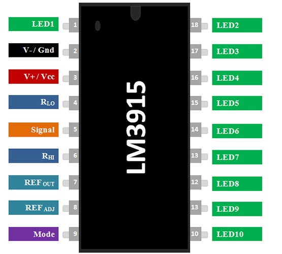
Pin LED (10 - 18) & Pin1 - connect the cathode part of the LED to the IC Pin.
PIN VS/GND connect the Ground pin of the supply to the ground pin of the IC
PIN VCC The VCC pin of the IC connects source voltage to this pin. Max operating voltage 25V.
RLO Voltage divider low level input.
SIG Analog Signal input pin, based on the gain parameter the LED is controlled.
RLH High level input voltage for potential divider
REF OUT Output Reference Voltage used set the limiting factor of the LED
REF ADJ Input Voltage Reference Adjust pin.
Mode Used to switch the input between dot mode and bar mode.
Components Required to Build LED VU Meter
The components required to build the LED VU Meter is simple and can be found in local shops
- Yellow LED 5mm - 8
- Red LED 5mm - 2
- 1K Resistor - 1
- 10K Pot - 1
- Soldering Wire
- 1mm copper wire
Circuit Diagram - LED VU Meter

The circuit diagram of the LED VU meter is very simple and easy to understand. If you look at the pinout of the. LM3915 is a digital IC that is used to create a visual display of sound volume, often called a VU meter. It works by breaking down an audio signal into 10 equal parts and comparing each part to an internal reference voltage. The chip has 10 output pins, each one corresponding to an LED. The voltage level at each output pin is set using a voltage divider. When an audio signal is fed into the chip, it is first rectified to a DC voltage, and then passed through the resistor network. As the voltage of the audio signal changes, the voltage at each output pin also changes. When the voltage at a particular output pin exceeds the reference voltage, the corresponding LED will light up. This gives a visual representation of the volume of the audio signal. To demonstrate the circuit we have used a simple PAM8403 based audio amplifier and a speaker.
Different Projects using LEDs and LM3915 LED Driver IC

If you are looking for a cool LED based project then this project is for you. Because in this project we have made a RGB LED tree that will change color randomly.

If you are looking for some unique and funky projects, then this project is for you, because in this project we have built RBG goggles that you can wear and be the showstopper of any party.

If you are looking for RGB led based tutorial then this project is for you because in this project we have done a detailed explanation of the WS2812B OLED Display.
