

The main aim of this mini-project is to demonstrate the working of a PIR motion-based light bulbs. This is to mainly minimize energy consumption and save electricity bills.
Sometimes people forget to turn off the light bulbs, this leads to a small waste of electricity. What if a few people around the world did the same thing and imagine how much electricity is wasted.
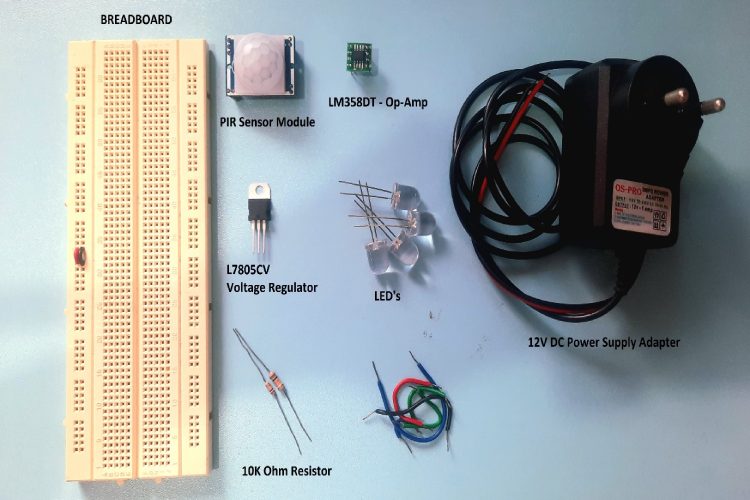
Components Used:
- L7805CV - Voltage Regulator
- LM358DT - Op-Amp
- PIR Motion Sensor Module
- 9V/12V DC Power Adapter or Battery.
- 2 - Resistor 10k Ohm
- LED Bulbs
- Breadboard & Few Wires.
Kindly Note: This demo project was built for the World Energy Challenge 2023. I used both the LM358DT Operational Amplifier and the LM7805 voltage regulator from STMicroelectronics. Both components are purchased from Digikey as per contest rules.
Circuit Diagram:

Connections are pretty simple here. Let us see the connections of each component one by one.
Power Source & 5V Regulator:
- A source of DC 12V/9V is given to the inputs of the 5V voltage regulator. Positive to Pin 1 (IN), which is the input of the regulator, and negative to the Pin2 (Ground) of the voltage regulator.
- The Output Pin3 of the voltage regulator is connected to the bread board that acts as a 5V Source for components like PIR Sensor, Voltage Divider and OP-AMP.
Voltage Divider:
- Two resistors of 10k ohm are connected in series between the 5V supply and Ground which acts as a voltage divider to provide 2.5V to the Pin2 (Inverting Input) of the OP-AMP.
OP-AMP:
- Here LM358 OP-AMP has two dual inputs for operational amplification, but here we will use only one.
- So, the Pin2 (Inverting Input) is connected to the voltage divider and Pin3 (Non-Inverting Input) is connected to the Output from the PIR Sensor Module.
- While Pin4 is connected to GND and Pin8 is connected to a 5V power supply.
- Finally, Pin1 (which is an output pin) connects to the Positive Terminals of the LED.
PIR Sensor Module: While the VCC pin of the PIR module is connected to a 5V Power Supply and GND to the GND, the output pin is already connected to the Non-Inverting Input of the OP-AMP.
LED Lights: Here I have connected fours LEDs to the Output pin1 of the OP-AMP.
Working:
After the connections, turn on the 9V Power Supply and wait a few seconds for the PIR sensor to stabilize. After that, the LED lights should go off. Now if you move your hands or objects in front of the PIR sensor you can see the LED lights going ON.
So how does it work?
- It’s simple. The PIR Sensor, when a motion is detected, it provides output to the OP-AMP of voltage (like 3.5V) to the (Non-Inverting) Pin3 which is higher than the voltage at, the (Inverting) Pin2 which has a 2.5V voltage divided.
- So, OP-AMP compares both the inputs and produces an output voltage at the output pin 1 which drives the LEDs. Similarly, when the voltage at pin3 drops less than the voltage at the pin2, then the LED lights going OFF.
- This is the behavior of an OP-AMP, which compares two inputs and provide output.
Improvements:
- This kind of light bulbs can be used in bulb portable cabins, solar lights, portable toilets etc.
- This light bulb can be combined with an LDR sensor and light bulbs can be turned off during the daytime when natural light is present.
- Control the brightness of the light according to the darkness.