

What is DC?
In elementary school, we learned that everything is made by atoms. This is a product of three particles: Electrons, Protons and Neutrons. As the name suggest Neutron does not have any charge whereas Protons are positive and Electrons are negative.
In atom, electrons protons and neutrons stay together in a stable formation, but if by any external process the electrons are separated from atoms they will always want to settle in the previous position thus it will create attraction towards protons. If we use these free electrons and push it inside a conductor which forms a circuitry, the potential attraction produces the potential difference.
If the flow of electron does not change his path and is in unidirectional flows or movements inside a circuit it is called as DC or Direct Current. DC Voltage is the constant voltage source.
In case of Direct Current, the polarity will never reverse or changed with respect to time, whereas the flow of current can vary with time.
As in reality, there is no perfect condition. In case of the circuit where free electrons are flowing, it is also true. Those free electrons do not flow independently, as the conducting materials are not perfect to let the electrons to flow freely. It does oppose the flow of electron by a certain rule of restrictions. For this issue, every electronics / electrical circuit consist three basic individual quantities which is called as V I R.
- Voltage (V)
- Current (I)
- And Resistance (R)
These three things are the basic fundamental quantities which appear almost in all cases when we see or describe something or making something which is related with Electrical or Electronics. They both are well related but they have denoted three separate things in Electronics or Electrical Fundamentals.
What is Current?
As previously stated, free separated electrons flow inside the circuitry; this flow of electrons (charge) is called as Current. When a voltage source applied across a circuit, the negative charge particles continuously flow at a uniform rate. This current is measured in Amperes as per SI unit and denoted as I or i. As per this unit 1 Ampere is the quantity of electricity carried in 1 second. The base unit of charge is coulomb.
1A is 1 coulomb of charge carried in a circuit or conductor in 1 second. So the Formula is
1A = 1 C/S
Where, C is denoted as coulomb and S is second.
In practical scenario, the electrons flow from the negative source to the positive source of the power supply, but for better circuit related understanding conventional current flow assumes that the current flows from the positive to the negative terminal.
In some circuit diagrams, we will often see that few arrows with I or i is pointed the flow of currents, which is the conventional flow of current. We will see use of current on Wall switch board as “Maximum 10 Ampere rated” or in the phone charger “maximum charge current is 1 Ampere” etc.
Current is also used as prefix with sub multiple as Kilo amps (103V), milli-amps (10-3A), micro-amps (10-6A), nano-amps (10-9A) etc.
What is Voltage?
Voltage is the potential difference between two points of a circuit. It does notify the potential energy stored as electrical charge in an electrical supply point. We can denote or measure the voltage difference between any two points in circuit nodes, junction etc.
The difference between two points called as potential difference or voltage drop.
This Voltage drop or potential difference is measured in Volts with the symbol of V or v. More Voltage denotes more capacity and more holds on the charge.
As described before Constant Voltage source is called as DC voltage. If the Voltage changes periodically with time, it is an AC Voltage or Alternating Current.
One Volt is by definition, the consumption of energy of one joule per electric charge of one coulomb. The relationship is as described
V = Potential Energy / Charge
Or
1V = 1 J/C
Where, J is denoted as Joule and C is coulomb.
One Volt voltage drop occurs when a current of 1 amp flow through resistance of 1 ohm.
1V = 1A / 1R
Where A is Ampere and R is resistance in ohm.
Voltage also used as a prefix with sub-multiple as Kilovolt (103V), milivolt (10-3V), micro-volt (10-6V), nano-volt (10-9V) etc. Voltage is also denoted as negative voltage as well as positive voltage.
AC voltage is commonly found in home outlets. In India it is 220V AC, in USA it is 110V AC etc. We can get DC voltage by converting this AC to DC or from Batteries, Solar Panels, Various power supply units as well as phone chargers. We can also convert DC to AC using Inverters.
It is very important to remember that Voltage can exist without current as it is the voltage difference between two points or potential difference but current cannot flow without any voltage difference between two points.
What is Resistance?
As in this world, nothing is ideal, every material has certain specification to resists the flow of electrons when passing from it. The Capacity of resist of a material is its resistance which is measured in Ohms (Ω) or Omega. Same as the Current and voltage, the resistance also has prefix for sub-multiple like Kilo-ohms (103Ω), mili-ohms (10-3Ω), mega-ohms (106Ω) etc. Resistance cannot be measured in negative; it is only a positive value.
The resistance notifies whether the material from which the current is passing is a good conductor means low resistance or a bad conductor means high resistance. 1Ω is a very low resistance compared with 1M Ω.
So, there are materials which have very low resistance and are a good conductor of the electricity. Like, copper, Gold, silver, Aluminum etc. On the other hand there are several materials which have very high resistance thus a bad conductor of electricity such as Glass, Wood, Plastic, and due to high resistance and bad electricity conducting capabilities, they are mainly used for insulation purpose as an insulator.
Also, special types of materials widely use in electronics for its special capabilities to conduct electricity between bad and good conductors, It’s semiconductors, the name implies it’s nature, semi-conductor. Transistors, diode, Integrated circuits are made using semiconductor. Germanium and silicon are widely used semiconductor material in this segment.
As discussed before resistance cannot be negative. But resistance has two particular segments, one is in linear segment and the other is in non-liner segment. We can apply specific boundary related mathematical calculation to calculate the resistance capacity of this linear resistance, on the other hand non-linear segmented resistance do not have proper definition or relations between voltage and current flow between this resistors.
Ohms Law and V-I Relationship:
Georg Simon Ohm aka Georg Ohm is a German physicist found a proportional relationship between Voltage drop, Resistance and Current. This relationship is known as Ohms Law.
In his finding, it is stated that the current passing through a conductor is directly proportional to the voltage across it. If we convert this finding into mathematical formation we will see that
Current (Ampere) = Voltage/ Resistance
I (Ampere) = V / R
If we know any of the two values from those three entities, we can find the third one.
From the above formula, we will find the three entities, and the formula will be:-
|
Voltage |
V = I x R |
Output will be Voltage in Volt (V) |
|
Current |
I = V / R |
Output will be Current in Ampere (A) |
|
Resistance |
R = V / I |
Output will be Resistance in Ohm (Ω) |
Let’s see the difference of this three using a circuitry where load is resistance and Am-meter is used to measure Current and Volt-meter is used to measure voltage.
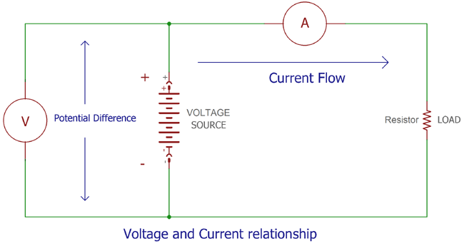
In the above image, an Ammeter connected in series and providing the current to the resistive load, on the other hand a volt meter connected across the source to measure voltage.
It’s important to remember that an ammeter is need to be 0 resistance as it supposed to provide 0 resistance on the current flowing through it, and for this to happen, an ideal 0 ohm ammeter is connected in series, but as voltage is the potential difference of two nodes, the voltmeter is connected in parallel.
If we change the current of the voltage source or the voltage of the voltage source or the load resistance across the source linearly and then measure the units, we will produce below result:
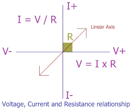
In this graph If R = 1 then the current and Voltage will increase proportionally. V = I x 1 or V = I. so if resistance is fixed then the voltage will increase with the current or the vice versa.
What is Power?
Power is either created or consumed, in an electronic or electrical circuitry the power rating is used to provide information about how much power the circuitry consumes to make a proper output of it.
As per the rule of nature, Energy cannot be destroyed, but it can be transferred, like Electrical energy converted to Mechanical Energy when Electricity applied across a Motor, or Electrical energy converted to heat when applied on a Heater. Thus a Heater need Energy, which is power, to provide proper heat dissipation, that power is rated power of the heater at maximum output.
Power is denoted with the symbol of W and it is measured in WATT.
Power is the multiplied value of the voltage and current. So,
P = V x I
Where, P is power in watt, V is Voltage and I is Ampere or current flow.
It also has sub prefix like Kilo-Watt (103W), mili-Watt (10-3W), mega-Watt (106W) etc.
As the Ohms Law V = I x R and the Power Law is P = V x I, so we can put the value of V in power law using V = I x R formula. Then the power law will be
P = I*R*I
Or
P = I2R
By arranging the same thing we can find the least one thing when other one is not available, the formulas are rearranged in the below matrix:
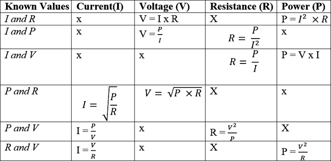
So each segment consists three formulas. In any of the cases if resistance became 0 then the current will be infinity, it is called the short-circuit condition. If Voltage became 0 then the current does not exist and the wattage will be 0, if the current became 0 then the circuit is in open circuit condition where the voltage is present but not the current thus again wattage will be 0, If wattage is 0 then no power will be consumed or produced by the circuitry.
Electron Flow concept
Current flows by charge attractions. In reality, as Electrons are negative particle and they flow from negative terminal to positive terminal of the power source. So in actual circuitry, Electron current flow from negative terminal to the positive terminal, But in conventional current flow as we described before we assume that current is flowing from positive to negative terminal. In the next image we will understand the flow of current very easily.
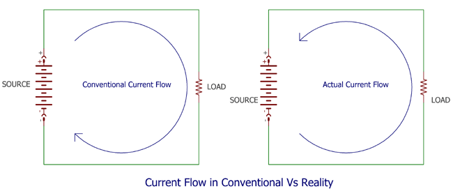
Whatever the direction is, it’s make no effect on the current flow inside a circuitry, It is easier to understand the conventional current flow from positive to negative. Single direction Current flow is DC or Direct Current and which alternate its direction called as Alternating Current or AC.
Practical Examples
Let’s see two examples to understand the things better.
1. In this circuit, a 12V DC source is connected across a 2Ω load, calculate the power consumption of the circuit?
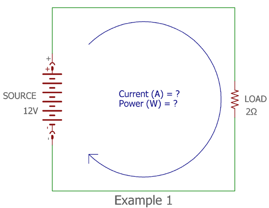
In this circuit, the total resistance is load resistance so the R = 2 and the input voltage supply is 12V DC so the V = 12V. The current flow in the circuitry will be
I = V / R
I = 12 / 2 = 6 Amperes
As Wattage (W) = Voltage (V) x Ampere (A) the total wattage will be 12 x 6 = 72Watt.
We can also calculate the value without Ampere.
Wattage (W) = Power = Voltage2 / Resistance
Power = 122 / 2 = 12*12 / 2 = 72 watt
Whatever the formula is used, the output will be same.
2. In this circuit total power consumption across the load is 30 Watt, if we connect 15V DC supply, how much current is required?
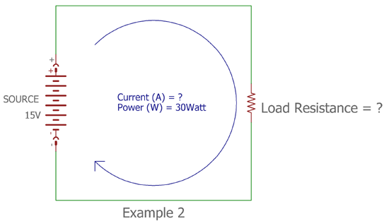
In this circuitry the total resistance is unknown. The input supply voltage is 15V DC so the V = 15V DC and the power flowing through the circuitry is 30W, So, the P = 30W. The current flow in the circuitry will be
I = P / V
I = 30 / 15 2 Amperes
So, Powering up the circuitry at 30W, we need 15V DC power source which is capable to deliver 2 Ampere of DC current or more as the circuitry requires 2Amp current.

Awesome