

As we all know Raspberry Pi is a wonderful Developing platform based on ARM microprocessor. With its high computational power and development options it can work out wonders in hands of electronics hobbyists or students. To learn more about a Raspberry Pi and how it works, let us try building a Line Follower Robot using Raspberry Pi.
If you are interested in robotics then you should be very familiar with the name “Line Follower Robot”. This robot is capable of following a line, just by using pair of sensor and motors. It might not sound efficient to use a powerful microprocessor like Raspberry Pi to build a simple robot. But, this robot gives you room for infinite development and robots like Kiva (Amazon warehouse robot) are an example for this. You can also check our other Line Follower Robots:
Materials Required:
- Raspberry Pi 3 (any model should work)
- IR Sensor (2Nos)
- DC Gear Motor (2Nos)
- L293D Motor Driver
- Chaises (You can also build your own using cardboards)
- Power bank (Any available power source)
Concepts of Line Follower
Line Follower Robot is able to track a line with the help of an IR sensor. This sensor has a IR Transmitter and IR receiver. The IR transmitter (IR LED) transmits the light and the Receiver (Photodiode) waits for the transmitted light to return back. An IR light will return back only if it is reflect by a surface. Whereas, all surfaces do not reflect an IR light, only white the colour surface can completely reflect them and black colour surface will completely observe them as shown in the figure below. Learn more about IR sensor module here.

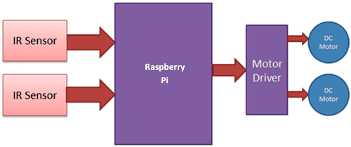
Now we will use two IR sensors to check if the robot is in track with the line and two motors to correct the robot if its moves out of the track. These motors require high current and should be bi-directional; hence we use a motor driver module like L293D. We will also need a computational device like Raspberry Pi to instruct the motors based on the values from the IR sensor. A simplified block diagram of the same is shown below.
These two IR sensors will be placed one on either side of the line. If none of the sensors are detecting a black line them they PI instructs the motors to move forward as shown below
If left sensor comes on black line then the PI instructs the robot to turn left by rotating the right wheel alone.
If right sensor comes on black line then the PI instructs the robot to turn right by rotating the left wheel alone.
If both sensors comes on black line, robot stops.
This way the Robot will be able to follow the line without getting outside the track. Now let us see how the circuit and Code looks like.
Raspberry Pi Line Follower Robot Circuit Diagram and Explanation:
The complete circuit diagram for this Raspberry Pi Line Follower Robot is shown below

As you can see the circuit involves two IR sensor and a pair of motors connected to the Raspberry pi. The complete circuit is powered by a Mobile Power bank (represented by AAA battery in the circuit above).
Since the pins details are not mentioned on the Raspberry Pi, we need to verify the pins using the below picture
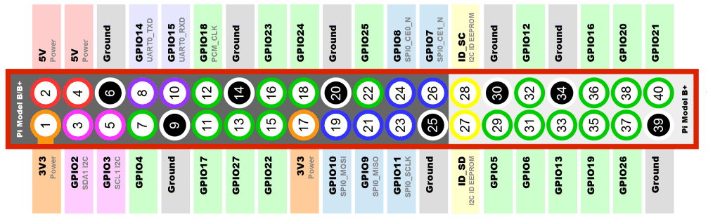
As shown in the picture the top left corner pin of the PI is the +5V pin, we use this +5V pin to power the IR sensors as shown in the circuit diagram (red wired). Then we connect the ground pins to the ground of the IR sensor and Motor Driver module using black wire. The yellow wire is used to connect the output pin of the sensor 1 and 2 to the GPIO pins and 3 respectively.
To drive the Motors, we need four pins (A,B,A,B). This four pins are connected from GPIO14,4,17 and 18 respectively. The orange and white wire together forms the connection for one motor. So we have two such pairs for two motors.
The motors are connected to the L293D Motor Driver module as shown in the picture and the driver module is powered by a power bank. Make sure that the ground of the power bank is connected to the ground of the Raspberry Pi, only then your connection will work.
Programming your Raspberry PI:
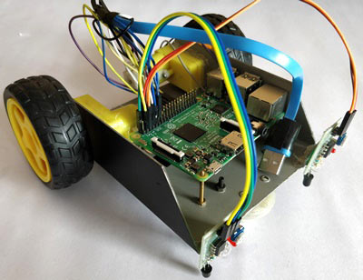
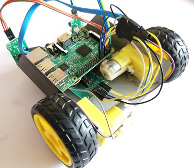
Once you are done with your assembly and connections your robot should look something like this.
Now, it is time to program our bot and get it running. The complete code for this bot can be found at the bottom of this tutorial. Learn more about Program and run code in Raspberry Pi here. The important lines are explained below
We are going to import GPIO file from library, below function enables us to program GPIO pins of PI. We are also renaming “GPIO” to “IO”, so in the program whenever we want to refer to GPIO pins we will use the word ‘IO’.
import RPi.GPIO as IO
Sometimes, when the GPIO pins, which we are trying to use, might be doing some other functions. In that case, we will receive warnings while executing the program. Below command tells the PI to ignore the warnings and proceed with the program.
IO.setwarnings(False)
We can refer the GPIO pins of PI, either by pin number on board or by their function number. Like ‘PIN 29’ on the board is ‘GPIO5’. So we tell here either we are going to represent the pin here by ‘29’ or ‘5’.
IO.setmode (IO.BCM)
We are setting 6 pins as input/output pins. The first two pins are the input pins to read the IR sensor. The next four are the output pins out of which first two is used to control the right motor and the next two for the left motor.
IO.setup(2,IO.IN) #GPIO 2 -> Left IR out
IO.setup(3,IO.IN) #GPIO 3 -> Right IR out

IO.setup(4,IO.OUT) #GPIO 4 -> Motor 1 terminal A
IO.setup(14,IO.OUT) #GPIO 14 -> Motor 1 terminal B

IO.setup(17,IO.OUT) #GPIO 17 -> Motor Left terminal A
IO.setup(18,IO.OUT) #GPIO 18 -> Motor Left terminal B
The IR sensor outputs “True” if it is over a white surface. So as long as both the sensor says True we can move forward.
   if(IO.input(2)==True and IO.input(3)==True): #both white move forward
        IO.output(4,True) #1A+
        IO.output(14,False) #1B-

        IO.output(17,True) #2A+
        IO.output(18,False) #2B-
We have to make a right turn if the first IR sensor comes over a black line. This is done by reading he IR sensor and if condition is satisfied we stop the right motor and rotate left motor alone as shown in the code below
elif(IO.input(2)==False and IO.input(3)==True): #turn right
        IO.output(4,True) #1A+
        IO.output(14,True) #1B-

        IO.output(17,True) #2A+
        IO.output(18,False) #2B-
We have to make a left turn if the second IR sensor comes over a black line. This is done by reading he IR sensor and if condition is satisfied we stop the left motor and rotate right motor alone as shown in the code below
elif(IO.input(2)==True and IO.input(3)==False): #turn left
        IO.output(4,True) #1A+
        IO.output(14,False) #1B-

        IO.output(17,True) #2A+
        IO.output(18,True) #2B-
If both the sensor comes over a black line, it means that the robot has to stop. This can be done by making both the terminals of the motor to be true as shown on the code below
   else:  #stay still
        IO.output(4,True) #1A+
        IO.output(14,True) #1B-

        IO.output(17,True) #2A+
        IO.output(18,True) #2B-
Raspberry Pi Line Follower in Action:
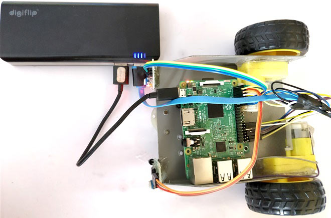
Upload the python code for line follower to your Raspberry Pi and run it. We need a portable power supply, a power bank in this case becomes handy hence I have used the same. The one that I am using comes with two USB ports so I have used to power the PI and other to Power Motor Driver as shown in the picture below.
Now all that you have to do is set up your own black colour track and release your bot over it. I have used a black colour Insulation tape to create the track you can use any black colour material, but make sure your ground colour is not dark.
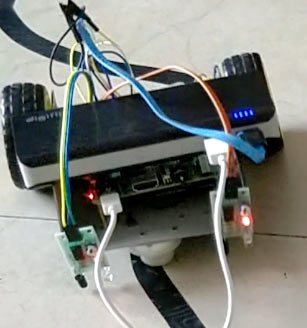
The complete working of the bot can be found at the video given below. Hope you understood the project and enjoyed building one. If you have any questions post them on the comment section below.
import RPi.GPIO as IO
import time
IO.setwarnings(False)
IO.setmode(IO.BCM)
IO.setup(2,IO.IN) #GPIO 2 -> Left IR out
IO.setup(3,IO.IN) #GPIO 3 -> Right IR out
IO.setup(4,IO.OUT) #GPIO 4 -> Motor 1 terminal A
IO.setup(14,IO.OUT) #GPIO 14 -> Motor 1 terminal B
IO.setup(17,IO.OUT) #GPIO 17 -> Motor Left terminal A
IO.setup(18,IO.OUT) #GPIO 18 -> Motor Left terminal B
while 1:
if(IO.input(2)==True and IO.input(3)==True): #both while move forward
IO.output(4,True) #1A+
IO.output(14,False) #1B-
IO.output(17,True) #2A+
IO.output(18,False) #2B-
elif(IO.input(2)==False and IO.input(3)==True): #turn right
IO.output(4,True) #1A+
IO.output(14,True) #1B-
IO.output(17,True) #2A+
IO.output(18,False) #2B-
elif(IO.input(2)==True and IO.input(3)==False): #turn left
IO.output(4,True) #1A+
IO.output(14,False) #1B-
IO.output(17,True) #2A+
IO.output(18,True) #2B-
else: #stay still
IO.output(4,True) #1A+
IO.output(14,True) #1B-
IO.output(17,True) #2A+
IO.output(18,True) #2B-
Comments
regarding ir sensor module
cant we just use ir sensor instead of whole module?
Motor drive
I bought a L293D Arduino motor shield. Can it be implemented in this project?
I want dwnld this projects
I want dwnld this projects for pdf plz provide me a link
motor driver description
hey..can you send the motor driver connection. how u connected power bank supply to motor in real time image

Hey,
How thin do you think you could make the line and still be able to accurately track the line?