

Raspberry Pi is an ARM architecture processor based board designed for electronic engineers and hobbyists. The PI is one of most trusted project development platforms out there now. With higher processor speed and 1 GB RAM, the PI can be used for many high profile projects like Image processing and Internet of Things.
For doing any of high profile projects, one need to understand the basic functions of PI. We will be covering all the basic functionalities of Raspberry Pi in these tutorials. In each tutorial we will discuss one of functions of PI. By the end of this Raspberry Pi Tutorial Series, you will be able to do high profile projects by yourself. Go through below tutorials:
- Getting Started with Raspberry Pi
- Raspberry Pi Configuration
- LED Blinky
- Raspberry Pi Button Interfacing
- Raspberry Pi PWM generation
- Controlling DC Motor using Raspberry Pi
- Stepper Motor Control with Raspberry Pi
- Interfacing Shift Register with Raspberry Pi
In this tutorial, we will Interface an ADC (Analog to Digital Conversion) chip to Raspberry Pi. We know all the parameters of analog, means there vary continuously over time. Say for an instance temperature of the room, the room temperature varies with time continuously. This temperature is provided with decimal numbers. But in digital world, there are no decimal numbers, so we need to convert the Analog value to Digital value. This conversion process is done by ADC technique. Learn more about ADC here: Introduction to ADC0804
ADC0804 and Raspberry Pi:
Normal controllers have ADC channels but for PI there are no ADC channels provided internally. So if we want to interface any analog sensors we need an ADC conversion unit. So for that purposes we are going to Interface ADC0804 with Raspberry Pi.
ADC0804 is a chip designed to convert analog signal into 8 bit digital data. This chip is one of the popular series of ADC. It’s an 8bit conversion unit, so we have values or 0 to 255 values. With a measuring voltage of maximum 5V, we will have a change for every 19.5mV. Below is the Pinout of ADC0804:
Now another important thing here is, the ADC0804 operates at 5V and so it provides output in 5V logic signal. In 8 pin output (representing 8bits), every pin provides +5V output to represent logic’1’. So the problem is the PI logic is of +3.3v, so you cannot give +5V logic to the +3.3V GPIO pin of PI. If you give +5V to any GPIO pin of PI, the board gets damaged.
So to step-down logic level from +5V, we will be using voltage divider circuit. We have discussed Voltage Divider Circuit previously look into it for further clarification. What we will do is, we use two resistors to divide +5V logic into 2*2.5V logics. So after division we will give +2.5v logic to PI. So, whenever logic ‘1’ is presented by ADC0804 we will see +2.5V at the PI GPIO Pin, instead of +5V.
Learn more about GPIO Pins of Raspberry Pi here and go through our previous tutorials.
Components Required:
Here we are using Raspberry Pi 2 Model B with Raspbian Jessie OS. All the basic Hardware and Software requirements are previously discussed, you can look it up in the Raspberry Pi Introduction, other than that we need:
- Connecting pins
- 220Ω or 1KΩresistor (17 pieces)
- 10K pot
- 0.1µF capacitor (2 pieces)
- ADC0804 IC
- Bread Board
Circuit Explanation:
It works on supply voltage of +5v and can measure a variable voltage range in 0-5V range.

The connections for interfacing ADC0804 to Raspberry PI, are shown in the circuit diagram above.
The ADC always have lots of noise, this noise can greatly affect the performance, so we use 0.1uF capacitor for Noise Filtration. Without this there will be lot of fluctuations at output.
The chip works on RC (Resistor-Capacitor) oscillator clock. As shown in circuit diagram, C2 and R20 form a Clock. The important thing to remember here is the capacitor C2 can be changed to a lower value for higher rate of ADC conversion. However with higher speed there will be decrease in accuracy. So if the application requires higher accuracy, choose the capacitor with higher value and for higher speed choose the capacitor with lower value.
Programming Explanation:
Once everything is connected as per the circuit diagram, we can turn ON the PI to write the program in PYHTON.
We will talk about few commands which we are going to use in PYHTON program,
We are going to import GPIO file from library, below function enables us to program GPIO pins of PI. We are also renaming “GPIO” to “IO”, so in the program whenever we want to refer to GPIO pins we will use the word ‘IO’.
import RPi.GPIO as IO
Sometimes, when the GPIO pins, which we are trying to use, might be doing some other functions. In that case, we will receive warnings while executing the program. Below command tells the PI to ignore the warnings and proceed with the program.
IO.setwarnings(False)
We can refer the GPIO pins of PI, either by pin number on board or by their function number. Like ‘PIN 29’ on the board is ‘GPIO5’. So we tell here either we are going to represent the pin here by ‘29’ or ‘5’.
IO.setmode (IO.BCM)
We are setting 8 pins as input pins. We will detect 8 bit of ADC data by these pins.
IO.setup(4,IO.IN)
IO.setup(17,IO.IN)
IO.setup(27,IO.IN)
IO.setup(22,IO.IN)
IO.setup(5,IO.IN)
IO.setup(6,IO.IN)
IO.setup(13,IO.IN)
IO.setup(19,IO.IN)
In case the condition in the braces is true, the statements inside the loop will be executed once. So if the GPIO pin 19 goes high, then the statements inside the IF loop will be executed once. If the GPIO pin 19 does not goes high, then the statements inside the IF loop will not be executed.
if(IO.input(19) == True):
Below command is used as forever loop, with this command the statements inside this loop will be executed continuously.
While 1:
Further explanation of Program is given in Code Section Below.
Working:
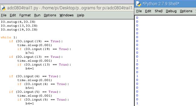
After writing the program and executing it you will see ‘0’on the screen. ‘0’means 0 volts at input.
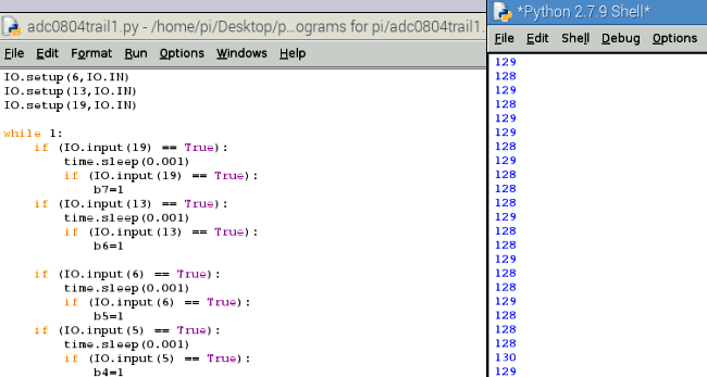
If we adjust the 10K pot connected to the chip, we will see the change in the values on the screen. The values on the screen keep scrolling continuously, these are the digital values read by PI.
Say if we get the pot to the midpoint, we have +2.5V at the ADC0804 input. So we see 128 on the screen as shown below.
For +5V analog value, we will have 255.
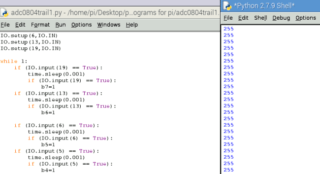
So, by varying the pot we vary the voltage from 0 to +5V at the ADC0804 input. With this PI read values from 0-255. The values are printed on the screen.
So we have Interfaced ADC0804 to Raspberry Pi.
import RPi.GPIO as IO # calling for header file which helps us use GPIO’s of PI
import time # calling for time to provide delays in program
IO.setwarnings(False) # do not show any warnings
x=1
b0 =0 # integers for storing 8 bits
b1 =0
b2 =0
b3 =0
b4 =0
b5 =0
b6 =0
b7 =0
IO.setmode (IO.BCM) # programming the GPIO by BCM pin numbers. (like PIN29 as‘GPIO5’)
IO.setup(4,IO.IN) # initialize GPIO Pins as input
IO.setup(17,IO.IN)
IO.setup(27,IO.IN)
IO.setup(22,IO.IN)
IO.setup(5,IO.IN)
IO.setup(6,IO.IN)
IO.setup(13,IO.IN)
IO.setup(19,IO.IN)
while 1: # execute loop forever
if (IO.input(19) == True):
time.sleep(0.001)
if (IO.input(19) == True):
b7=1 # if pin19 is high bit7 is true
if (IO.input(13) == True):
time.sleep(0.001)
if (IO.input(13) == True):
b6=1 # if pin13 is high bit6 is true
if (IO.input(6) == True):
time.sleep(0.001)
if (IO.input(6) == True):
b5=1 # if pin6 is high bit5 is true
if (IO.input(5) == True):
time.sleep(0.001)
if (IO.input(5) == True):
b4=1 # if pin5 is high bit4 is true
if (IO.input(22) == True):
time.sleep(0.001)
if (IO.input(22) == True):
b3=1 # if pin22 is high bit3 is true
if (IO.input(27) == True):
time.sleep(0.001)
if (IO.input(27) == True):
b2=1 # if pin27 is high bit2 is true
if (IO.input(17) == True):
time.sleep(0.001)
if (IO.input(17) == True):
b1=1 # if pin17 is high bit1 is true
if (IO.input(4) == True):
time.sleep(0.001)
if (IO.input(4) == True):
b0=1 # if pin4 is high bit0 is true
x = (1*b0)+(2*b1)
x = x+(4*b2)+(8*b3)
x = x+(16*b4)+(32*b5)
x = x+(64*b6)+(128*b7) # representing the bit values from LSB to MSB
print ( x) # print the ADC value
b0=b1=b2=b3=b4=b5=b6=b7=0 # reset values
time.sleep(0.01) # wait for 10ms
Comments
Add rain water sensor
Can i add rain water sensor in the circuit to read it as analogue input. Please teach me and reply as soon as possible.

in python can u get me the sample code for to read the readings in water flow meter please reply me as soon as possible and mainly harware connections with mcp3008