
Water tank overflow is a common problem which leads to the wastage of water. Though there are many solutions to it like ball valves which automatically stop the water flow once the tank gets full. But being an electronics enthusiastic wouldn’t you like an electronic solution for it? So here is a simple and handy DIY water alarm project tutorial that will guide you to make a circuit which will detect the water level and will raise an alarm upon getting the water tank full or a preset level.
This simple transistor based water level indicator circuit is very useful to indicate the water levels in a tank. Whenever tank gets filled, we get alerts on particular levels. Here we have created 4 levels (low, medium, high and full), we can create alarms for more levels. We have added 3 LEDs to indicate initial three levels (A, B, C), and one Buzzer to indicate FULL level (D). When tanks gets filled completely we get beep sound from Buzzer. If you want to improve the project by adding a display and automatic motor on-off control then you can simply add a microcontroller like Arduino to sense the water changes and control the display and motor accordingly, if you want more details about that project you can check out the Arduino based water level indicator and controller project.
Components Required for Water Level Alarm Circuit
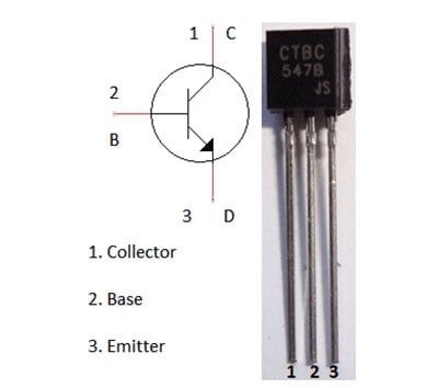
- 4 - BC547 transistors
- 6 - 220 ohm resistors
- 3 - Colour LEDs - red, green, and yellow
- 1 – Buzzer
- 5 - 9v battery + battery clip
- Breadboard
Water Tank Overflow Alarm Circuit
The complete circuit diagram for the water overflow alarm project can be found below. As you can see the circuit is simple and easy to build as it only has few basic components like transistors, resistors, LEDs and a buzzer

We can consider this whole circuit as 4 small circuits, each one for indicating/alarming, when a particular level (A,B,C,D) of water have been reached.
When water level reaches to point A, circuit with RED LED & transistor Q1 gets completed and RED LED glows. Similarly when water level reaches to point B, circuit with YELLOW LED and transistor Q2 gets completed and Yellow LED glows, same goes with point C. And finally when tank gets full (Point D), circuit with buzzer gets completed and buzzer starts beeping.
Low Water Level Alarm Circuit - Working
Here we are using transistor (of NPN type) as a Switch. Initially there is no voltage applied to the base of the Transistor Q1 and the transistor is in OFF state and no current is flowing through collector and emitter and LED is OFF (See below diagram to understand Transistor Pin structure).
When the water level reaches to Point A in the tank, the positive side of the battery gets connected to the base of the Transistor Q1 through the water. So when a positive voltage has been applied to the base of the Transistor Q1, it gets into ON state and current starts flowing from collector to emitter. And RED LED glows.
You can see resistors (R1, R2, R3) at the base of each transistor, which is used to limit the maximum Base current. Generally a transistor gets its ON state fully when a voltage of 0.7 V is applied to the base. There are also resistors (R4, R5, R6) with each of the LEDs, to drop the voltage across LEDs, otherwise LED may blow up.
Same phenomenon happens when water level reaches to Point B. As soon as water level reaches to Point B, a positive voltage gets applied to the Transistor Q2, it gets ON and current started flowing through YELLOW LED, and LED glows. With same principle, GREEN LED glow when water level reaches to Point C.And finally Buzzer beeps when water level reaches to D.
Note that Left most wire in the tank must be lengthier than other four wires in the tanks, because this is the wire which is connected to positive voltage.
Comments
POwer Supply
Can I use a 9V/2A output from a (AC to DC) transformer instead of the battery ?
2A is more for this circuit,
2A is more for this circuit, you should lower the current with some current limiting circuitry.
Are you talking about power
Are you talking about power supply instead of battery. You can use 5v 500mA adapter or check this circuit: 0-24v 3A Variable Power Supply
Hi,
Hi,
Good project thanks for sharing. I have a question....I am doing a similar project but with capacitive oil level Sensor which measures the quantity of oil in a Tank. I also have to measure low (1/4), medium (1/2), high (3/4) and full (1) using two capacitive parallel plates. Can I use almost the same circuit diagram?? Or how would it be like??
Oil conductivity is much
Oil conductivity is much lesser than water, so it may not work in Oil tank.
need help with concepts
Can you please tell me the role of the transistors. The transistor configuration is for a switch then how can it act as a amplifier?
Please read all the previous
Please read all the previous comments before asking questions, we might have answered them already.
as soon as i connect battery
as soon as i connect battery the buzzer is buzzing. what could be the problem for that? please help thanks
This led is ok but buzzer not
This led is ok but buzzer not working
Use 5 volt power supply
Sir,
Can I use 5 V DC power supply from solar system, instead of 9 V to supply two circuits indicators.
Is the circuit should be modified for 5 v DC or not.
how battery does this circuit
how battery does this circuit requires?
water level indicater
Can we use only one transister 148 and two resistance of 100 and 470 k om
It'super and amazing way to
It'super and amazing way to indicate water level.
Cable lenght
Hi, I just want to ask how long can be cables A,B,C,D which leads to water tank. Because I want try this 9V solution but I need at least 10 meters long cables because of distance to water tank.
Thanks in advance.
May i use same circuit on motor
Sir,
Can I use motor by replacing the buzzer ??
Is any possibilities here when the water will have reached the top of the tank then the motor will off??
I mean the pump motor which is using to enlarge the water level of the tank!!
Can I use motor by replacing the buzzer ??
If yes, how can i made necessary changes in circuit..?
And due to long distance; may i use wireless...?
Please revert me with necessary suggestions.
Thanks
You can replace the buzzer
You can replace the buzzer with motor using Relay and you can make it wireless using GSM or wifi module with some Microcontroller. Check our other tutorials for using GSM or wifi.
buzzer not work
sir ,
I use 12 volt transformer and bridge rectifier instead of 9V battery but i'm facing problem with my buzzer its not work properly ,its giving wheezing sound I'd checked my circuit several time its wiring is okay and My led's also work well , And One more problem when i take 20 feet 5 core thin telephone wire i'm facing current leakage problem between wires, LED's glow dim even without touching any Ground and positive. Please any suggestion
What is the current output of
What is the current output of you transformer, high current can damage the parts. Try the same configuration with short wire and share the results.
water lever indication
can we use 9v d.c suppy to water lever indication, place on 9v battry
w.l.i
yes i am also make this project and i have copleted with good working
i think u may miss 1 thing negative suply is conect to other ends of all leds and buzer and also positive is goes into the ground of water which provide continue suply for each leds
so check ur circuits
thank u
great....its working in large
great....its working in large tank...
I made this with smps and an
I made this with smps and an a88 chip.but how it worked can explain its working with smps and a88 chip
Sir reply me fast on the above email
Wonderful it has worked,
Wonderful it has worked, awesome. I extended it with 7 level indicator using cat 6 ethernet cable for the connectivity from tank to ground floor, used 9V power adaptor for continue monitoring. working superb.
if this circuit does not work
if this circuit does not work in purified or distilled water.....then what should we do for the pure water..level indication..
Considering water resistance
Water resistance is 18.2 MΩ / cm, how base current to this transistor will be provided????
hi, please i wish to know if
hi, please i wish to know if the water used can be replaced with fuel?
the project is working but
the project is working but the whole circuit burnt why any body can help me out?
water level indicator
what size wire needed if LED diodes and battery(ies) are mounted 20 meters from water reservoir, with additional 4 meters depth of reservoir
Please read the previous
Please read the previous comments before asking, your question might has been already answered.
where is available this componant
where is available this componant
Everything works fine but
Everything works fine but when the water level reaches the last sensor, the other two leds dim. Also the buzzer produces an extremely faint sound. The wire is approximately 15 meters. All the other components are as prescribed. PLEASE HELP!!!!
water level indicator
please How can I combine switch that will stop the pumping to this project sir
You need to attach a Relay
You need to attach a Relay for AC motor pump to stop.
I was trying to make this in
I was trying to make this in Proteus everything is working except the buzzer?
sir I want a reverse process
sir I want a reverse process like if probes is in water my buzzer of otherwise it will on so what can I do. I tried many times with different circuits using the not gate and by using PNP transistor the problem is when i touch the probes it will work and when i put them in water it wouldn't what can i do please help??
PNP transistor should work
PNP transistor should work but you need to change the circuit according to PNP transistor.
Water level indicator
Sir, i want use this water level indicator for a long meter over 100 m for water wells in the ground. Are this circuit will be work well
Sir can use this type
Sir can use this type tarnsistor(BC547 45V 0.1A NPN Transistors TO-92)
Project work
Please sir am a mechanical student and I have seen this project as a good project and I wish to use it as my project work, please sir can I use it.
Confused about r4,r5,r5 register
When transistor is on then emitter and collector is connected.I think there has no connection between base and led. So tell me uses and how r4,r5 and r3 registers are working?
Any problems in change 9v to
Any problems in change 9v to 12v 1A ADAPTER
If you want to use a 12V
If you want to use a 12V adapter use a regulator IC like 7805 or 7806 to regulate the voltage to lower level.
About Resistors Value in Watt.
Admin, I want the exact value of the 220 Ohm resistor in watt...!
Can I use 12volts battery
Can I use 12volts battery instead of 9 volts?
No, if you want to use a 12V
No, if you want to use a 12V battery use a regulator like 7805 and get regulated +5V and use it as your power source
Water level indicator
such a GREAT article to work on. Thankyou for sharing this information. I hope this will help many people. you can also check out my article
sir whether i can use 330ohm
sir whether i can use 330ohm resistor and BC547 transistor kindly help me out
plz help me out where i can
plz help me out where i can use 330ohm and BC547 instead of that
Water level indicator
I have made the water level indicator which worked fine for a few days . But now the LEDs keep glowing even when the water level goes below the set level . Earlier the LEDs kept glowing only for 20-30 seconds after the level went down the set level
Neccessity of positve voltage wire?
Why we need a separate positive voltage wire to into the tank, is it neccessary to have that wire?
Without transistors
I saw some circuits without transistors, resistors directly connected to water. What is the differences.
It is working all types of
It is working all types of water but it does not work in corporation water supply. Any Solution ?
thank you so much for your
thank you so much for your post about this project it's a good idea.
but please may you give us the block diagram of that circuit water level indicator alarm
i need your help plzzzz
i need your help plzzzz
when i will runn this project may i use motor pump? i want to do this project as s6 final project at school
Yes you can what is the
Yes you can what is the specification of the pump?
Level in water tank.
Since water will be used as conductor in the circuit, can we use the water from the tank or is there possibility to get electrocuted?
No there are no chance for
No there are no chance for electrocution since the voltage and current rating is small
Sir, I have a doubt
Good project.congrats. sir I have a doubt,
1. why using transistor. can i do this project only using battery, resistor,and L E D(that is, without use transistor)? What is the use of transistor?
2. What is the its principle of this project?
Water level circuit
What will happen if power suplly increased to 12 volt DC. What are the parts required to be changed keeping intact other components except the resistors. Please advice.
12v buzzer
Can I use 12volt buzzer in this circuit.If yes, then how?

This question is already answered in above comments, please check. Further use PNP transistor BC557 in place of BC547 and reverse the order of LED/buzzer.