

Piano is developed by connecting a 555 timer ASTABLE multivibrator with variable frequency to a speaker. Piano is a wonderful musical instrument and one can make a cheap one using 555 timer IC chip. This concept of piano is achieved by making the timer generate 5-15 different kind of sounds. The different sounds are generated through timer by allowing it to run as free running mode or astable mode or square wave mode, with variable frequency output option.
Circuit Components
- +9 to +12 supply voltage
- 555 timer IC
- 100Ω, 10KΩ (5pieces) and 2K2Ω resistors
- 100KΩ pot or variable resistor
- 0.1µF and 10µF capacitors, 100µF capacitor (not a compulsory, connected in parallel to power)
- Buttons(6 pieces)
- Speaker (8Ω,0.5WATT).
Circuit Diagram and Explanation
Before going for circuit, one should understand how the frequency output of square wave generated by free running timer can be changed.
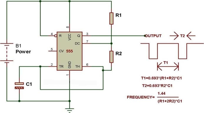
The figure shown below is a mere square wave generator. In the third formula it can be see that the frequency of output square wave is inversely related to R2 (in the piano circuit it is a button network). So if R2 increases the frequency decreases. This changing frequency with changing resistance when connected to speaker we get different sounds.
The below figure shows the circuit diagram of piano or ASTABLE with different frequencies. In this circuit consider a case, a button first from left is pressed, the resistance between pin7 and pin6 goes as (100+POT resistance). For example consider the frequency generated here is 1KHz square wave and so we get a tone. Now if the second from left is pressed, the resistance between pin7 and pin6 goes as (100+Pot resistance+10K resistance), now here the frequency of square wave generated is different from that of first one as the effective resistance have changed between pin7 and 6. With this frequency change of square wave, we get a different tone to the first one. This is how every button is set up in the circuit.

So every time a button is pressed a different amount of resistance gets connected to generate a different frequency square wave and so we get a different tone for different button. This concept is used to generate the whole combinations of tones form the piano.
To make this more interesting (and usable too!), the number of tones in this piano circuit can be increased by connecting more resistor buttons configuration. So we can get more than ten tones depending on one’s choice.
The pot is to adjust for a pleasant tone. The 10K resistors can be replaced with any kind of resistances depending on the convenience.
Comments
The Answers are very obvious:
The Answers are very obvious:
1. Yes, all 10k will be added when pressing the left most button.
2. yes, its important, so that resistance between 6 and 7 never goes to Zero.
3. Astable mode (already mentioned many times in the explanation)
recomendatio
hello i highly appreciate the project,but i would like also to recommend that you shoul provide a documents hosts of all things mentioned here,so that we can review whenever we are in need of this
Hey my piano circuit made as
Hey my piano circuit made as given do not sounds clear .What should I do for it?
yongmei 6300
i have a piano yongmei 6300 for eleven years since 2006. it had a problem and i need to fix this if you can help.
all small wires has been cut by rates and i can not easily sold them back, so i need a help , a schematic board on how to remix the wire back so that it can work again.
please help......
is it 2K2Ω ? or 22kΩ??
is it 2K2Ω ? or 22kΩ??
is must be 22k right?
Yeah few people use these
Yeah few people use these type of representations
2K2Ω. The place where K is suppose to get a decimal point. So,
2.2KΩ which equlas to 2200Ω as rightly pointed out.
Similarly 1M5Ω means 1.5MΩ

hello,
thank u very much for this nice subject . but there is something i don't get it?
in the circuit diagram explanation are you sure about the (left button)? what i see when pressing the first button on the left is that all the 10k resistors will be included to the connection (effective resistance) ??
question2: is it important to have the 100 ohm resistor (the one series with the POT)?
question3: what is the mode of the 555 timer operating here??
please if you could answer me these question ill be so thankful