

Quiz is an important event in any school/College institution to test the knowledge of the participants. In order to increase the difficulty, the spontaneity of the participants is also tested in which the reaction time of the participants also matters. So, to indicate the person who is ready first to answer the question has to push the buzzer. It is also hard for a judge or the organizer to identify the first person who pushed the buzzer ON, since the participants race to answer the question. So Here we have added one feature in which if someone presses the buzzer first then all the remaining participant‘s buzzer gets disabled and the buzzer will not sound again until the reset button is pressed.
Here we have built a Quiz Buzzer Circuit using the versatile 555 Timer IC which is for 3 persons but we can increase the number of participants or players by increasing the no of 555 ICs or by combining two or more ICs together.
There are three popular configurations of 555 timer IC,
They differ by the number of stable states in the circuit. In our case we need Bistable Multivibrator Mode where there are two stable states. The first state is enabled when the participant presses the button and the second state is to reset the timer. Hence, the configuration used here is bistable multivibrator. Here in this Simple Quiz Buzzer Circuit we are about to use three timers. Hence the number of participants is three and the single organizer.
Components Required:
- 555 timer IC – 3Nos
- Tactile switch – 4Nos
- BC547 – 1No.
- Buzzer – 1No.
- LED – 6Nos
- Diode – 3Nos
- Breadboard
- Resistors (10kὨ - 4Nos; 1kὨ - 7Nos)
- Connecting wires
School/College Quiz Circuit Diagram and Explanation:

Here in the circuit diagram of the School/College quiz Buzzer circuit using 555 IC, we have used three 555 timer IC in bistable configuration. The important part is each 555 IC will have their own stable state controlled by separate buttons which will be accessed by the participants. Another single button controls the other stable state of the all the timer ICs in common which is accessed by the organizer to reset the entire circuit. When any of the buttons P1, P2, P3 is pressed the corresponding TRIGGER pin gets low and the timer shifts its stable state and the output pin of the corresponding timer goes high. And the Green LED of corresponding Participant turns on and buzzer starts beeping.
The operation is that when the first stable state of any one timer is set, it disables the remaining timers. This is because the forward biased diode connected to output pin of the set timers gets forward biased making the remaining button terminals go high. Hence, even if the other buttons are pressed after this, the corresponding timer’s pin sees only high signal. Hence, the buttons work only after resetting the entire circuit. The buzzer is controlled using NPN transistor BC547 whose control signal is the common TRIGGER to which buttons are connected. Also, the buttons are grounded through internal diode of transistor.
Working of Quiz Buzzer Circuit:
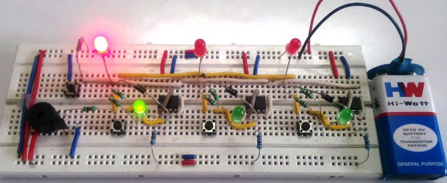
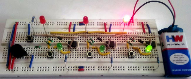
The whole circuit is powered by a 9V battery. Initially the circuit is in RESET condition and waiting for a TRIGGER signal. So, as soon the participant presses the button the corresponding timer changes its state and the output goes high and the buzzer sounds to indicate the button press. Below picture indicates that the button P1 is pressed and the remaining buttons will be disabled.
Now when the RESET button ORG is pressed the circuit goes to initial state and again waits for next TRIGGER.
The GREEN LED is to indicate the participant that he/she has pressed first. The RED LED is to indicate the organizer about the first person to press the button. Now when the third participant presses the button the corresponding LED goes high and the buzzer will sound.
This process can be continued to any number of times. If the buzzer is not needed in the circuit, the transistor BC547 and buzzer can be eliminated. But, the resistor connected to base of the transistor should be grounded directly. Or if anyone wants to add buzzer on each participant side then it can be added with a NPN transistor on PIN 3 of each 555 timer.
Comments
I think it is a normal buzzer
I think it is a normal buzzer, anyway i am sure you can use any normal buzzer in this project
The diode I have used above
The diode I have used above is 1N4007. You can also use 1N4148 or any lower value.
final report of this project
I want final report of this project. In that abstract then advantages, disadvanteges are needed.
Plz send me or comment on it. I want that abstract urgently help me
Quiz buzzer
I modified the circuit by using a buzzer for each timer, but doesn't seem to work. Also when I built it like yours ,there were problems like false triggering and p1,2and 3 overriding the reset pin. What could be the possible cause of these
The false triggering might
The false triggering might happen mostly due to the loose connection in the bread board. I too experienced it initially.
Secondly, if you are trying to use buzzer for each timer and find it not working properly then try to use a transistor for each buzzer whose base is controlled by the output of the timer. The buzzer connected in series to the 5V supply and transistor and then to ground. This might help.
Use of resistance
What is the exact use of resistances on the circuit?
Please send me your circuit
Please send me your circuit diagram of this project
requesting for video
sir! I want the video of making the quiz buzzer circuit.It's an urgent.
Hoping for quick response.
Resistors.
your circuit diagram is wrong, in the diagram it shows 4 10k ohms 1 1k ohms and 3 500 ohms. i dont understand where is the 7 1k ohms resistors ? please answer
But if you will look at the
But if you will look at the actual picture. He put 1 resistor at the reset button. And every led has resistors. And it has 6 leds. So that's why 7 resistor. But if you will follow his circuit diagram, it's correct but don't forget to put resistors in your led.
Diagam Accuracy
If the diagram is not correct, why did you publish it? Resistor sizes and locations are not the same between the components list and the circuit diagram. It is lazy and cruel to publish an incorrect circuit diagram. Lazy, because you could have changed the diagram to make it correct. Cruel because students who are learning about electronics will be confused and frustrated. Two parallel resistors in the photograph, one resistor in the circuit diagram. Please do good quality work, and do not publish the rough draft which contains errors.
One Minute Buzzer
Hi there. I need to design a circuit where the buzzer is only turned ON after one minute but im not sure how to start. Can you help me bro ?

What diode was used on the circuit?...