

One of the most commonly used sensors in Electronics is IR sensor (Infrared Sensor). IR sensor helps in detecting the heat and the motion of an object. In the infrared spectrum, all the objects emit some form of thermal radiations. These radiations are invisible to a human eye and can only be sensed or detected by an IR sensor. An IR sensor consists of IR Transmitter which is used for emitting IR rays and IR Receiver (Photodiode) which is used for detecting that emitted IR rays. Normally, the range of an IR radiation from a normal IR LED is 2~10cm with detection angle 35 °.
By using this Circuit, we can increase the range of emitted IR radiation up to 100cm. It means we can increase the IR transmitting distance multiple times using this Long Range IR Transmitter circuit. Here we have used multiple IR LEDs to increase the distance. Also learn here about How IR sensor works.
Material Required
- CD4047 IC
- IR LEDs – 3
- Transistor – BC547 and BC557
- MOSFET – BS170
- Potentiometer (10k)
- Capacitor (100uF-1; 470pF-1)
- Resistor (10k-2; 2k-1; 22ohm-1)
- Bread Board
- 9v supply input
- Connecting wires
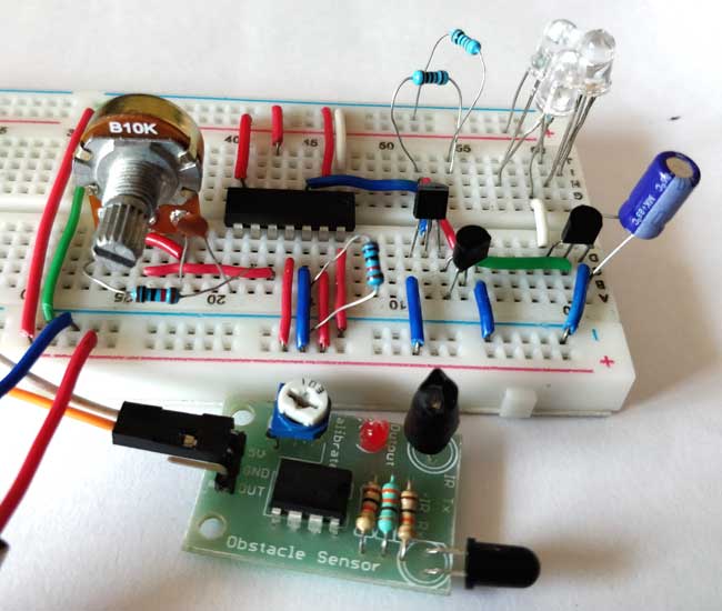
Circuit Diagram


CD4047 IC
The 4047 IC is one of the popular IC with low power consumption. It provides both Monostable (one-shot) and Astable (free running) operation. It has a wide range of input voltage (3v to 18v) and DC current input is up to ±10mA with a high operating temperature range of −55°C to +125°C. Here, we are using this IC to generate a oscillating square wave output whose frequency will be decided by resistor R3 and capacitor C1. You can use the IC for generating clock pulse for various applications. This IC is mainly used in Inverter circuit to generate Alternating current from DC current.
Application of this IC are Frequency discriminators, Timing circuits, Time-delay applications, Envelope detection, Frequency multiplication, and Frequency division.
Pin Diagram
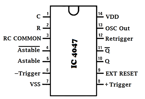
Pin configuration IC 4047
|
Pin No. |
Pin Name |
Description |
|
1 |
C |
Used to connect external capacitor |
|
2 |
R |
Used to connect external resistor |
|
3 |
RCC |
Common pin for connecting resistor and capacitor to it |
|
4 |
AST’(Astable bar) |
Low when used in Astable mode |
|
5 |
AST |
High when used in Astable mode |
|
6 |
-Trigger |
When used in Monostable mode we give High to Low transition to this pin |
|
7 |
Vss |
Ground pin of IC |
|
8 |
+Trigger |
When used in Monostable mode we give Low to High transition to this pin |
|
9 |
EXT RESET |
It’s an external reset pin. By giving a high pulse to this pin, it resets the output Q to low and Q’ to high |
|
10 |
Q |
Give normal high output |
|
11 |
Q’ |
Inverse output of pin 10, means it gives low output |
|
12 |
Retrigger |
Used in Monostable mode to simultaneously retrigger +trigger and –trigger pin |
|
13 |
OSC Out |
Gives oscillated output |
|
14 |
Vdd |
Positive input pin of IC |
MOSFET BS170
These components are designed to minimize on-state resistance in order to provide fast and reliable switching performance. BS170 can be used in various application requiring a DC current up to 500mA. Best suited for low voltage and low current applications such as small servo motor control, power MOSFET gate drivers and for other switching application. The Drain-Source and Gate-Source Voltage of BS170 is 60V maximum. The Operating and Storage Junction Temperature Ranges from−55 to +150 °C.
Pin Diagram
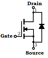
Pin Configuration
|
Pin No. |
Pin Name |
Description |
|
1 |
D |
Drain terminal of BS170 |
|
2 |
G |
Gate terminal, used of turn ON the BS170 |
|
3 |
S |
Source terminal of BS170 |
Working of Long Range IR Transmitter
The circuit helps us to increase the range of transmitting IR rays. We have used three IR LEDs in series for increasing the radiated power.
A resistor and capacitor are externally connected to the PIN 2 and PIN1 respectively, short with PIN 3 of 4047 IC. The combination of resistor and capacitor (RC) generates output with a certain oscillating frequency. Then this output is fed to the base of both the transistor Q1 and Q2.
IC4047 is generating 38KHz frequency, which is near to IR and RF remote control frequency. Then, modulating the incoming signal or data by using this frequency wave as a carrier wave. So, we get a high range of output at this frequency. Also, IC4047 is used to generate oscillating wave for transistor and MOSFET.
A MOSFET BS170 is used for increasing the circuit efficiency. The MOSFET acts as a switch and reduces the power loss. Power loss of transistor is high in comparison to the MOSFET, therefore we have used a MOSFET instead of transistor. A 100uF capacitor is used to avoid any dip during turning ON/OFF. It supplies extra charge during turning ON operation.
Also, a Darlington pair is made using NPN (BC547) and PNP (BC557) transistor for avoiding distortion of the gate drive input. As a MOSFET exhibits large capacitance across gate-source terminals.
The three IR LEDs are connected to the Drain of the MOSFET. As the gate terminal of MOSFET get signal it allows the MOSFET to conduct current through Drain to Source and LEDs start emitting IR rays in a higher range then a normal IR LED. Hence, we get an IR ray of long range which is sensed by an IR receiver, as shown in the video below.
