

To get a regulated power supply we use various voltage regulator ICs like 7805, 7812 etc but they all provide fixed value of output. For variable voltage regulation we already covered LM317 voltage regulator circuit. Today we are making Voltage Regulation Circuit using LM723. This is one of the popular IC used for the Voltage regulation.
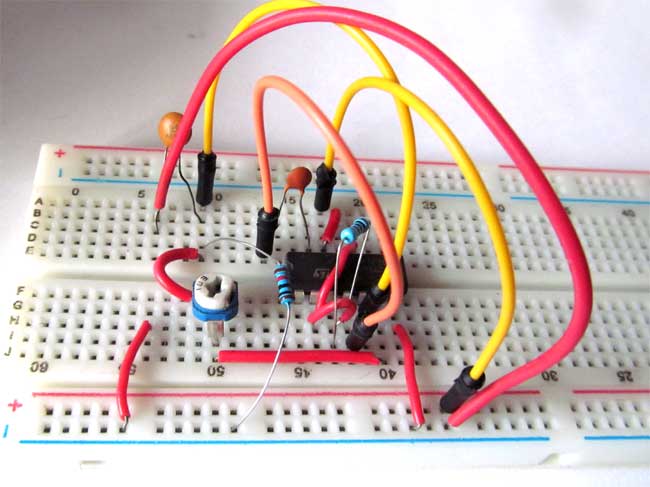
For this voltage regulator circuit using LM723 IC, we just need to add few resistors and capacitors with the IC as per the circuit diagram given below. By giving 9v input power supply, we will be able to adjust the regulated supply from 4v to 8v by using the potentiometer in the circuit. The benefit of using this IC is that it can provide an excessive quantity of current of up to 10A, by connecting an external pass transistor with proper circuitry.
The supply voltage of the LM723IC is maximum 40v and the output ranges from 3v to 37v with a 150mA of output current without using an external pass transistor.
Material Required
- LM723 voltage regulator IC
- Resistor-10k
- Capacitor (100pf, 0.1uf)
- Potentiometer-10k
- Connecting wires
- Battery 9v
Circuit Diagram

You can get the value of resistance R3 by the formula given in the datasheet of the IC LM723:
R3 = (R1*R2) / (R1+R2)
Note: This circuit is only for getting output voltage ranges from 2v to 7v maximum.
Voltage Regulator IC LM723
The LM723 is the adjustable voltage regulator IC designed for series regulator application, with a current output of 150mA without external pass transistor. If we use an transistor externally, it can able to provide up to 10A of current to drive any desired load up to this range. The input supply is 40v maximum and its output voltage ranges from 3v to 40v. The IC is also used in various applications like shunt regulator, current regulator. The IC having low standby current drain, which allow us to use the IC as linear or fold back current limiting, with an operating temperature ranges from -55 °C to 150 °C.
Pin diagram of LM723
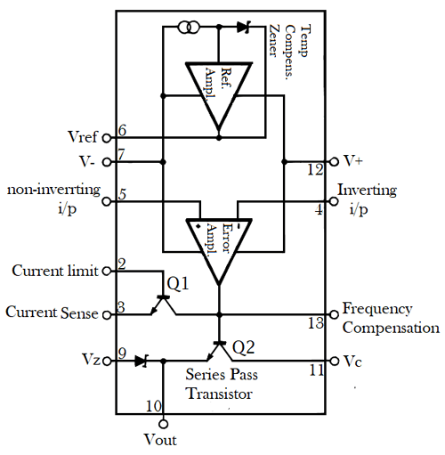
Pin configuration of LM723
|
Pin No. |
Pin Name |
Description |
|
1 |
NC |
Not connected |
|
2 |
Current Limit |
This is the base pin of current limiting transistor Q1, used for current limiting and to reduce the power dissipation at fault condition to reduce the risk of heating. |
|
3 |
Current Sense |
This is the emitter pin of the current limiting transistor Q1, used for current limiting and fold-back application. |
|
4 |
Inverting i/p |
This terminal is connected to the inverting pin of the error op-amp whose output is connected to Q2 transistor, helps in providing constant output voltage |
|
5 |
Non-inverting i/p |
This terminal is connected to the non-inverting pin of the error op-amp, used to provide reference voltage to the op-amp. |
|
6 |
Vref |
It is the reference output voltage of the IC, approx. 7.15v |
|
7 |
-Vcc |
Ground pin of IC |
|
8 |
NC |
Not connected |
|
9 |
Vz |
Connected with the anode terminal of the Zener diode and cathode of Zener diode is connected to Vout, it is generally used for making negative voltage regulators |
|
10 |
Vout |
This terminal provides an output voltage range from 3v to 37v with a current rating of 150mA. |
|
11 |
Vc |
Connected with collector input of series pass transistor. Supplied directly through source when not connected with the series pass transistor. |
|
12 |
V+ |
Positive supply of IC |
|
13 |
Frequency Compensation |
This terminal is used for connecting a capacitor with inverting input of the IC to reduce the noise. As per internal connection it is the output pin of error amplifier. Typically the value of capacitor is 100pf or you can use datasheet for the same. |
|
14 |
NC |
Not connected |
Working of LM723 Voltage Regulator Circuit:
A voltage of 9v is provided to the reference amplifier through V+ pin (PIN 12) of LM723 to get a constant output voltage at Vref Pin 6. The reference voltage is then transferred to the non-inverting Pin 5 of the IC by connecting potentiometer and capacitor with it. The voltage at the non-inverting pin is used to compare with inverting pin voltage. If the voltage at non-inverting input greater than inverting pin then the series pass transistor get forward biased and allow the current to flow through the collector to emitter and we get the output voltage through PIN 10. In this circuit, we are using potentiometer RV1 instead of R1. We can adjust the voltage as per the requirement by moving the potentiometer RV1.
The formula for finding the output voltage of this circuit, according to Voltage Divider Rule, is:
Vout = Vref * (R2 / RV1+R2)
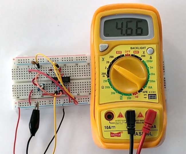
The maximum output can be generated by this circuit is 7v and minimum is 2v, for getting higher or lower than this range of output voltage, there are many circuits diagrams presents in datasheet which gives the different range of output voltage to be needed.
Comments
Current of 10A I doubt no,
Current of 10A I doubt no, may be you should use a switching circuit
LM-723
I can't believe they're still using these. Wow! I worked for a company called Power One when I got out of the air force in 1977 and went to work for them in 1978. They made regulated power supplies using the 723 with outputs from 0.5 amps to 50 amps and voltages from 5 to 250 VDC, yes 250VDC using the 723 IC. And YES, 50 amps and the regulation was to within about 5 or so millivolts even on the 50A regulator. This is all before they figured out how to build switching supplies. They worked extremely well and incorporated over voltage protection and short circuit protection as you've mentioned. I still have one of their power supplies that didn't pass final inspection that I dug out of the trash bin. It was supposed to be a 15 VDC supplie but it wouldn't hold the voltage under load. It worked great at 13.5 for years though while I used it to maintain a 12 motorcycle battery in my living room that I operated a mobile style CB radio. I set up a current measuring resister .01 ohm and read the voltage drop across it to figure current into and out of the battery. If I didn't transmit for awhile the charge current would drop and drop till it was only 3 or 4 milliamps. I'm using a similar setup to power a mobile ham radio in my hobby room with a deep cycle battery and a battery tending charger.
Later on they started experimenting and finally producing switching power supplies and that was such a revelation. Light weight and simple in comparison. That 5VDC 50 amp supply must have weighed 10 pounds or more. It had a bunch of transistors, 2N3055 if I remember right, driven by a single 2N3055 which was in turn driven by the 723 IC. Some of their supplies used a "Darlington" type transistor that was actually one transistor driving a second transistor inside one case I think they were a 2N6055. Boy if that isn't scraping the bottom of the memory box I don't know what is.
Blow me down 5V to 250VDC at
Blow me down 5V to 250VDC at 50A without a swithcing circuit..... That should be one killer bulky circuit. I wonder how they managed to milk 50A out these poor souls.. Do you have a picture of your supply?

I have tried this one out successfully and it has worked out for me but could their be another IC that can input 9V and it outputs 13V and A current of 10A?