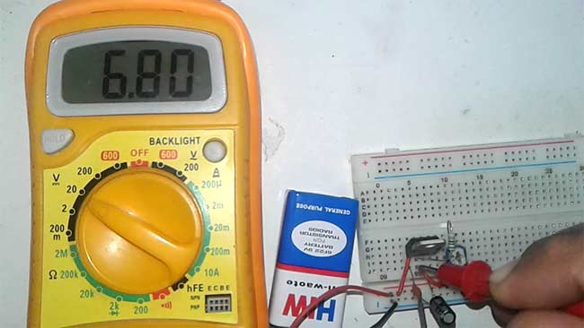
Whenever we need a constant and specific value of voltage without fluctuation we use voltage regulator IC. They provide a fixed regulated power supply. We have 78XX (7805, 7806, 7812 etc) series voltage regulators for positive power supply and 79XX for negative power supply. But what if need to vary the power supply voltage, so here we have Variable Voltage Regulator IC LM317. In this tutorial we will show you how to get the variable regulated Voltage from the LM317 IC. With a small circuitry attached with LM317 we can get variable voltage up to 37v with 1.5A max current. The output voltage is varied by varying the resistor connected to LM317’s adjustable pin.
Required Components
- LM317 voltage regulator IC
- Resistor (240ohm)
- Capacitor (1uf and 0.1uf)
- Potentiometer (10k)
- Battery (9v)
Circuit Diagram

LM317 Voltage regulator IC
It’s an adjustable three-terminal voltage regulator IC, with a high output current value of 1.5A. The LM317 IC helps in current limiting, thermal overload protection and safe operating area protection. It can also provide float operation for High voltage application. If we disconnect the adjustable terminal still LM317 will helpful in Overload protection. It’s having a typical line and load regulation of 0.1%. This is also a Pb-free device.
Its operating and storage temperature is in range of -55 to 150 °C, and provide a maximum output current of 2.2A. We can provide input voltage in the range of 3v-40v DC and it can give output voltage of 1.25 v to 37v which we can vary according to the need by using two external resistors on adjustable PIN of LM317. These two resistors works as voltage divider circuit used to increase or decrease the output voltage. Check here the 12v Battery Charger Circuit using LM317
PIN Diagram of LM317

Pin Configuration
|
PIN NO. |
PIN Name |
PIN Description |
|
1 |
Adjust |
We can adjust the Vout through this pin, by connecting to resistor divider circuit. |
|
2 |
Output |
Output voltage pin (Vout) |
|
3 |
Input |
Input voltage pin (Vin) |
Voltage Calculation for LM317
Firstly, you have to decide what output you want. As the LM317 having an output voltage range of 1.25v to 37v DC. We can adjust the output voltage by two external resistor connected through the adjustable pin of the IC. If we talk about the input voltage it can be in range of 3 to 40v DC.
“Output will depend on the external resistor only, but the input voltage should always be greater than (minimum of 3v) the needed output voltage”. Generally the recommended value of resistor R1 is 240ohms (but not fixed you can change it too as per your requirement), we can vary the resistor R2.
You can directly find the value of the output voltage or resistor R2 by using the formula below:
Vout = 1.25 {1 + (R2 / R1)}
R2  =  R1   {(Vout / 1.25) – 1}
You can directly use LM317 Calculator for fast calculation of resistor R2 and output voltage.
Let’s take an example, the value of R1 will be the recommended value 240ohm and R2 we are taking of 300ohms, so what will be the output voltage:
Vout = 1.25* {1+ (300/240)} = 2.8125v
You can check the live demonstration Video below.
Working of LM317 Voltage Regulator Circuit

This voltage regulator circuit is very simple. The capacitor C1 used for the filtering of DC input voltage and further fed to the Vin pin of the LM317 voltage regulator IC. The adjustable pin is connected with the two external resistor, and connected with the Vout pin of the IC. The capacitor C2 is used for the filtering the output voltage received from the Vout pin. And then the output voltage received across the capacitor C2. Check the full working Video below.


