

The process of converting alternating current into direct current is rectification. Any offline power supply unit has the block of rectification which converts either the AC wall receptacle source onto high voltage DC or stepped down AC wall receptacle source into low voltage DC. The further process will be filtering, DC-DC conversion, etc., So, in this article we are going to discuss all the operations of Half-wave rectifier with circuit diagram.
The nature of the AC voltage is sinusoidal at a frequency of 50/60Hz. The waveform will be as below.

Now Rectification is the process of removing the negative part of the Alternate Current (AC), hence producing the partial DC. This can be achieved by using diodes. Diodes only allow current to flow in one direction. For understanding we can split the waveform into positive half cycle and negative half cycle.When the above voltage is supplied through a diode, the conduction takes place during positive half cycle only. Thus, below will be the waveform.

Working of Half Wave Rectifier:
In Half wave Rectifier, we remove the negative Half Cycle of AC wave by using one diode, while in Full Wave Rectifier we convert the negative half cycle of AC into positive cycle using 4 diodes. Let us now consider an AC voltage with lower amplitude of 15Vrms and rectify it into dc voltage using a single diode. The diode conducts only during positive half cycle. But, the output will be discontinuous pulsed positive DC voltage. It has to be further filtered to make it a pure DC with lesser ripple. Point to be kept in mind is all the voltage, current that we measure through DMM is rms in nature. Hence the same is considered in simulation also.


The output waveform above is as expected, a discontinuous pulsed DC waveform. In order to smoothen the waveform or to make it continuous we add a capacitor filter in the output. The working of parallel capacitor is to maintain a constant voltage at the output. It decides the amount of ripple present in the output.
With a 1uF capacitor filter:


Below waveform shows the reduction in ripple based on the value of capacitance ie., charge storing capacity.

Output waveforms : Red – 1uF ; Mustard green – 4.7uF ; Blue – 10uF ; Dark green – 47uF
Operation with capacitor :
During the positive half cycle, the diode is forward biased and the capacitor gets charged as well as the load gets supply. During negative half cycle the diode gets reverse biased and the circuit is open during which the capacitor supplies the stored energy in it. The more the energy storage capacity the lesser the ripple in the output waveform.
The ripple factor can be calculated theoretically by,
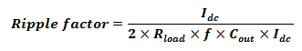
Let us calculate it for a any capacitor value and compare it with the above obtained waveforms.
Rload = 1kOhm; f= 50Hz; Cout = 1uF; Idc = 15mA
Hence,

The above waveform has a ripple of 11 Volts which is nearly same. The difference will be compensated at higher capacitor values. Besides, the efficiency is the major problem in half wave rectifier which is lesser than full wave rectifier. Generally the efficiency(ƞ) = 40%.
Practical Half Wave Rectifier Circuit on Breadboard:
The components used in half wave rectifier circuit are:
- 220V/15V AC step-down transformer.
- 1N4007 – Diode
- Resistor
- Capacitors
Here, for an rms voltage of 15V the peak voltage will be up to 21V. Hence the components to be used should be rated at 25V and above.
Operation of the circuit:
Step-down transformer:
The step down transformer consists of primary winding and secondary winding wound over laminated iron core. The number of turn of primary will be higher than the secondary. Each winding acts as separate inductors. When primary winding is supplied through an alternating source, the winding gets excited and flux will be generated. The secondary winding experiences the alternating flux produced by the primary winding which induces emf into the secondary winding. This induced emf then flows through the external circuit connected. The turns ratio and inductance of the winding decides the amount of flux generated from primary and emf induced in secondary. In the transformer used below
The 230V AC power supply from the wall receptacle is stepped down to 15V AC rms using a step-down transformer. The supply is then applied across the rectifier circuit as below.
Half Wave Rectifier Circuit Without filter:

Corresponding voltage across load is 6.5V because the average output voltage of the discontinuous waveform can be seen in the DMM.

Half Wave Rectifier Circuit With Filter:
When capacitor filter is added as below,

1. For Cout = 4.7uF, the ripple gets reduced and hence the average voltage increased to 11.9V

2. For Cout = 10uF, the ripple gets reduced and hence the average voltage increased to 15.0V

3. For Cout = 47uF, the ripple gets further reduced and hence the average voltage increased to 18.5V

4. For Cout = 100uF, so after this the waveform is finely smoothened and hence the ripple is low. The average voltage increased to 18.9V

