

The process of converting alternating current into direct current is rectification. Any offline power supply unit has the block of rectification which converts either the AC wall receptacle source into a high voltage DC or stepped down AC wall receptacle source into low voltage DC. The further process will be filtering, DC-DC conversion and etc. So, in this article we are going to discuss the operations of Full-wave rectifier. The full wave rectifier has a higher efficiency when compared to that of half wave rectifier.
The full wave rectification can be done by the following methods.
- Center tapped full-wave rectifier
- Bridge rectifier (Using four diodes)


If two branches of a circuit is connected by a third branch to form a loop, then the network is called a bridge circuit.Out of these two the preferable type is Bridge rectifier circuit using four diodes because the two diode type requires a center tapped transformer and not reliable when compared to bridge type. The diode bridge is also available in a single package. Some of the examples are DB102, GBJ1504, KBU1001 and etc.
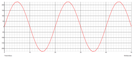
The bridge rectifier outweighs the reliability of half bridge rectifier in terms of the ripple factor reduction for the same filter circuit at output. The nature of the AC voltage is sinusoidal at a frequency of 50/60Hz. The waveform will be as below.
Working of Full Wave Rectifier:
Let us now consider an AC voltage with lower amplitude of 15Vrms ( 21Vpk-pk ) and rectify it into dc voltage using a diode bridge. The AC supply waveform can be split into positive half cycle and negative half cycle. All the voltage, current that we measure through DMM (Digital Multimeter) is rms in nature. Hence the same is considered in below Greenpoint simulation.

During the positive half cycle diodes D2 and D3 will conducting and during negative half cycle diodes D4 and D1 will be conducting. Hence, during both the half cycles the diode will be conducting. The output waveform after rectification will be as below.

In order to reduce the ripple in waveform or to make the waveform continuous we have to add a capacitor filter in the output. The working of the capacitor in parallel to load is to maintain a constant voltage at the output. Thus, the ripple in the output can be reduced.
With a 1uF capacitor as filter:

The output with filter of 1uF dampens the wave only to a certain extend because the energy storage capacity of 1uF is less. The below waveform show the result of filter.

Since the ripple is still present in output we are going to check the output with different capacitance values. Below waveform shows the reduction in ripple based on the value of capacitance ie., charge storing capacity.

Output waveforms : Green – 1uF ;Blue– 4.7uF ; Mustard green – 10uF ; Dark green – 47uF
Operations with capacitor:
During both the positive and negative half cycles, the diode pair will be in forward biased condition and the capacitor gets charged as well as the load gets supply. The interval of the instantaneous voltage at which the stored energy in capacitor is higher than the instantaneous voltage the capacitor supplies the stored energy in it.The more the energy storage capacity the lesser the ripple in the output waveform.
The ripple factor can be calculated theoretically by,
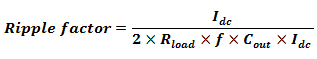
Let us calculate it for any capacitor value and compare it with the above obtained waveforms.
Rload = 1kOhm; f= 100Hz; Cout = 1uF; Idc = 15mA
Hence, Ripple factor = 5 volts
The ripple factor difference will be compensated at higher capacitor values. The efficiency of full wave rectifier is above 80% which is double that of a half wave rectifier.
Practical Full Wave Rectifier:
The components used in a bridge rectifier are,
- 220V/15V AC step-down transformer.
- 1N4007 – Diodes
- Resistors
- Capacitors
- MIC RB156
Here, for an rms voltage of 15V the peak voltage will be up to 21V. Hence the components to be used should be rated at 25V and above.
Operation of the circuit:
Step-down transformer:
The step down transformer consists of primary winding and secondary winding wound over laminated iron core. The number of turn of primary will be higher than the secondary. Each winding acts as separate inductors. When primary winding is supplied through an alternating source, the winding gets excited and flux will be generated. The secondary winding experiences the alternating flux produced by the primary winding which induces emf into the secondary winding. This induced emf then flows through the external circuit connected. The turns ratio and inductance of the winding decides the amount of flux generated from primary andemf induced in secondary. In the transformer used below
The 230V AC power supply from the wall receptacle is stepped down to 15V ACrms using a step-down transformer. The supply is then applied across the rectifier circuit as below.
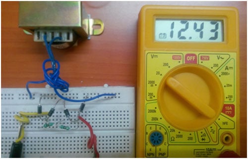
Full Wave Rectifier Circuit Without filter:
The corresponding voltage across load is 12.43V because the average output voltage of the discontinuous waveform can be seen in the digital multi-meter.
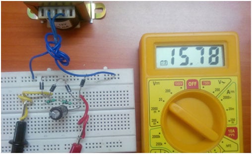
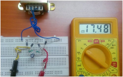
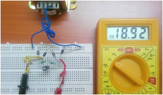
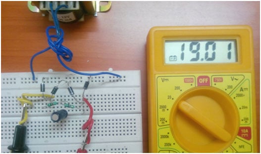
Full Wave Rectifier Circuit With Filter:
When capacitor filter is added as below,

1. For Cout = 4.7uF, the ripple gets reduced and hence the average voltage increased to 15.78V
2. For Cout = 10uF, the ripple gets reduced and hence the average voltage increased to 17.5V
3. For Cout = 47uF, the ripple gets further reduced and hence the average voltage increased to 18.92V
4. For Cout = 100uF, any value of capacitance greater than this will not have much effect, so after this the waveform is finely smoothened and hence the ripple is low. The average voltage increased to 19.01V

I would like to have the files to get the debug info for proteus
to simulate them and work for any specific application. Can be possible to be added?
Thanks