
Stun gun is a device which generates high voltage at it’s output by taking low voltage as input. Concept of this device is based on High volt inverter. Here we are building this Stun Gun circuit on PCB. Stun Gun can be dangerous and can cause serious damage if not used properly, we take no RESPONSIBILITY for any resulting actions. This stun gun circuit can also works in mosquito killer racket or insect zapper.
Components Required:
- DS965 NPN Transistor -1
- Fly back Transformer -1
- Push button -1
- LED -2
- PCB (ordered from EasyEDA)
- Terminal Block 2 pin -3
- Resistor 150k -1
- Resistor 1k -3
- Capacitor 1nF/3KV -2
- Capacitor 1000uF -1
- Capacitor 470nF/400V -1
- Capacitor 105/3KV -1
- Power Supply 3v-12v -1
- 1N4007 Diode -7
- Zenner diode 5.1v -1
- On/off switch -1
- Conducting net/ mosquito racket -1
Circuit Diagram and Explanation:

The circuit is built by using a Fly Back Transformer which is derived by a general NPN transistor. Transformer turn ratio for feedback coil, primary coil and secondary coil will be around 1:4:50. This circuit can be operated at 3v-12v. At 3v, transformer output will be around 1000-2000 volt without load. Then, we have used capacitor and general diode for coupling the output of transformer more times, device output voltage becomes near 3000-5000 volt without Load. User can also boost the voltage by changing turn ratio of transformer and some more capacitor and diodes. In controlling part of this circuit we have used a push button to trigger the Stun Gun, this push button completes the circuit when pressed.
When using 9v battery for this circuit, battery gets drained very fast so we have added a battery charger circuit for charging rechargeable battery. But
Note: If you are planning to give power supply form any adapter or from Arduino then you can safely remove the battery charger part at the left bottom of the circuit which consists 4 diodes, one zener diode, one 1000uf capacitor, one 470nf capacitor and one 150k resistor. We have also used Arduino power supply to demonstrate in the Video given in the end.
Working Explanation:
Whenever we press the trigger button then input circuit gets completed and input voltage gets applied to the transformer. Now transformer returns a feedback voltage from feedback winding. This feedback voltage is applied to transistor base continuously. Due to switch on and off by feedback voltage, transistor generate a frequency and works as oscillator. With the help of this oscillation, step up transformer converts low voltage to high voltage at transformer secondary winding then voltage is again boosted by using capacitor and diode circuit as shown in the circuit diagram above.
Circuit and PCB Design using EasyEDA:
To design this Stun Gun Circuit, we have chosen the online EDA tool called EasyEDA. We have previously used EasyEDA many times and found it very convenient to use compared to other PCB fabricators. Check here our all the PCB projects. Using EasyEDA, we can draw the schematics, simulate them before designing PCB and finally we can design PCBs. After designing the PCB, we can order the PCB samples by their low cost PCB fabrication services. They also offer component sourcing service where they have a large stock of electronic components and users can order their required components along with the PCB order. EasyEDA just launched its a new version v4.8.5, you can find all the new feature details here: EasyEDA v4.8.5. Its desktop version is also available to download, which can be downloaded from this link. They will provide the assembly service at the end of this year.
While designing your circuits and PCBs, you can also make your circuit and PCB designs public so that other users can copy or edit them and can take benefit from there, we have also made our whole Circuit and PCB layouts public for this Stun Gun Circuit, check the below link:
https://easyeda.com/circuitdigest/StunGun-ffea983966934d5097976fb2f342774c
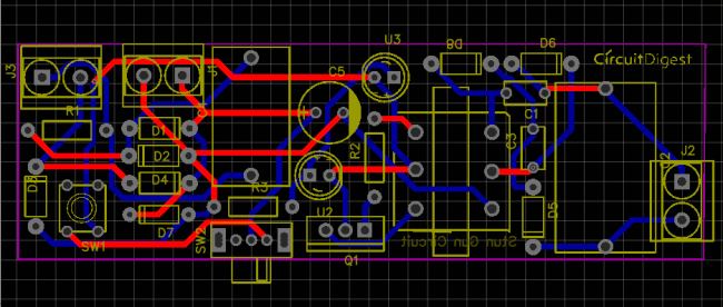
Below is the Snapshot of Top layer of PCB layout from EasyEDA, you can view any Layer (Top, Bottom, Topsilk, bottomsilk etc) of the PCB by selecting the layer form the ‘Layers’ Window.
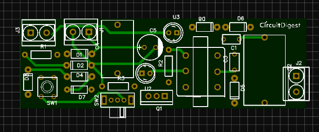
Below is the Photo View of PCB
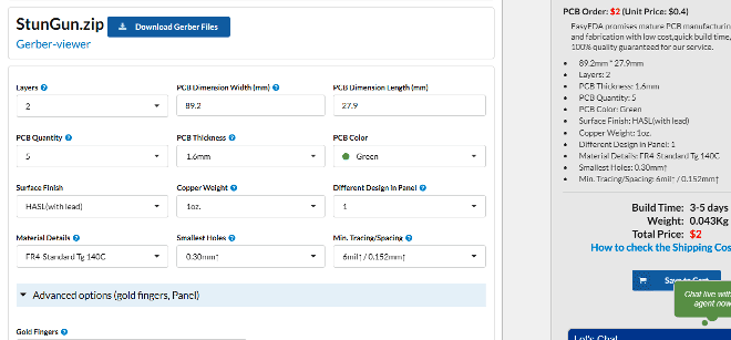
Calculating and Ordering Samples online:
After completing the design of PCB, you can click the icon of Fabrication output above. Then you will access the page PCB order to download Gerber files of your PCB and send them to any manufacturer, it’s also a lot easier (and cheaper) to order it directly in EasyEDA. Here you can select the number of PCBs you want to order, how many copper layers you need, the PCB thickness, copper weight, and even the PCB color. After you have selected all of the options, click “Save to Cart” and complete your order, then you will get your PCBs a few days later. And you may go with your local PCB vendors too with Gerber output of PCB layout. They are fabricating the PCB at very low rate which $2.
After few days of ordering PCB’s I got the PCB samples
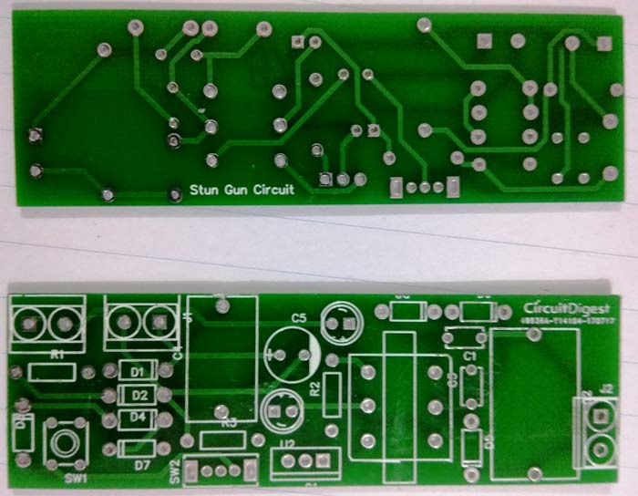
Soldering: after getting these pieces I mounted all the required components over the PCB to build a Stun Gun.
Comments
Transformer type
What is size of core ?
What is winding wire gauge and nos?
Clarify feedback and primary windings?
But i am dammed sure that like other this questions will remain unanswered?

i need 12v to 220v diagram and the component