

Here, we are going to show you how to make an LED Roulette Circuit using 555 timer IC, before starting the tutorial let you know about what the roulette is, it’s a casino game named after the French word which means little wheel. As same, here we are making a wheel (or circle) shaped led blinker, using 555 timer IC placed in Astable mode, and IC 4017 which is decade counter IC and small needful components.
Required Components
- 555 Timer IC
- Decade Counter IC 4017
- Resistors - 220 Ohm, 1k and 10k
- Capacitor - 10µF
- LEDs – 8
- Battery - 9v
- Breadboard and connecting wires
Circuit Diagram

Decade Counter IC 4017
The 4017 IC is a truly useful IC in project works, timer based games and in various DOCTRONICS construction kit like Light Chaser and Matrix Die. It’s having lots of useful application if we think, you can check all our 4017 IC related projects here.
If we talk about the technical part, it’s a CMOS decade counter decoder circuit. This IC is used to generate output in a sequence manner like it start from zero and goes up to 10. It shifts it output from one pin to another by applying clock pulse at PIN 14. First clock pulse makes first output PIN (PIN 3) HIGH, second clock pulse makes first PIN LOW and second PIN (PIN 2) HIGH, third clock pulse makes third PIN HIGH, and so on. So it creates sequential ON and OFF of all the 10 OUTPUT PINs which is needed in our LED Roulette circuit. Here this clock pulse is generated by 555 Timer IC in astable mode.
Pin Diagram
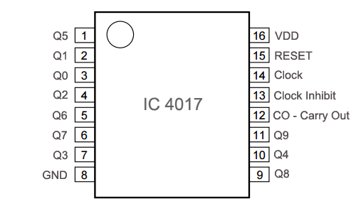
Pin Configuration
|
PIN NO. |
PIN Name |
PIN Description |
|
1 |
Q5 |
Output 5: It goes high when the counter reads 5th clock pulse |
|
2 |
Q1 |
Output 1: It goes high when the counter reads 1st clock pulse |
|
3 |
Q0 |
Output 0: It goes high when the counter reads 0th clock pulse |
|
4 |
Q2 |
Output 2: It goes high when the counter reads 2nd clock pulse |
|
5 |
Q6 |
Output 6: It goes high when the counter reads 6th clock pulse |
|
6 |
Q7 |
Output 7: It goes high when the counter reads 7th clock pulse |
|
7 |
Q3 |
Output 3: It goes high when the counter reads 3rd clock pulse |
|
8 |
GND |
Ground PIN |
|
9 |
Q8 |
Output 8: It goes high when the counter reads 8th clock pulse |
|
10 |
Q4 |
Output 4: It goes high when the counter reads 4th clock pulse |
|
11 |
Q9 |
Output 9: It goes high when the counter reads 9th clock pulse |
|
12 |
CO –Carry out |
Used to cascade another 4017 IC to makes it count upto 20, it is divide by 10 output PIN, we can count how much we want just by cascading the ICs through this pin and every IC will generate 10 outputs. |
|
13 |
CLOCK inhibit |
In operating condition this pin will remain at Low, beacause if this pin is High, will stop the pulse generation means it will be in freeze mode. |
|
14 |
CLOCK |
Clock input, for sequentially HIGH the output pins from PIN 3 TO PIN 11 |
|
15 |
RESET |
Active high pin, should be LOW for normal operation, setting HIGH will reset the IC (only Pin 3 remain HIGH) |
|
16 |
VDD |
Power supply PIN (5-12v) |
Working of LED Roulette Circuit
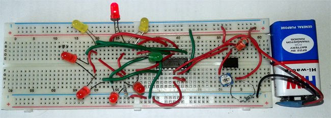
Now we will connect the LEDs in a roulette design (circle shape), as we used 8 LEDs which are connected by the output pins of the 4017 IC according to the sequence of output, start from zero and goes up to 10 but we are using only 8 output pins as the number of LEDs are 8 and its gets the clock pulse or pulse input from the 555 timer IC in Astable mode. As the LEDs start blinking we can adjust the speed of the blinking LEDs by setting the value of resistance through a potentiometer connected in the circuit because changing the value of resistance will change the oscillation frequency of the 555 timer IC, hence the rate of clock pulse. You can calculate the exact value of resistance and capacitance in the circuit for desired output clock pulse, with this 555 Astable Calculator.
Comments
Yes the circuit diagram is
Yes the circuit diagram is missing the 16th pin. And hence its assumed to be connected to Vcc... Thanks pushpak for the info

Hey bro I think you forgot to connect IC 4017 pin no 16 to Power supply I connected it in mine then only it worked