 Hi
Hi
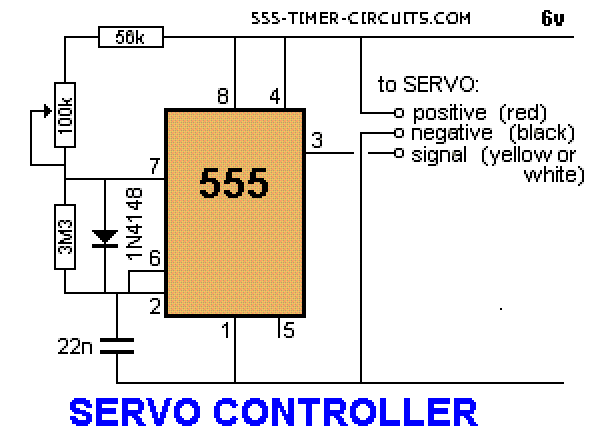
I am new to electronics forum and would like some advice on building the servo controller circuit in image.
I understand how to construct most of the circuit on the breadboard except for the wiring of the 100K variable resistor.
The 100K trim pot I am using has the usual three terminals but don’t know witch terminal to fit where .
If I understand it correctly the 56k resistor goes to the end of the pot track the other end to pin 7 pn the 555
but I dont know where the wiper terminal should go.
Any help welcome,
Regards
DGB

Hi Dale,in the circuit the 100K potentiometer is used as a variable resistor.So we have to connect it's wiper pin to one of it's fixed end.Hence now we will have only two pins,connect one fixed end of 100K potentiometer to 56K resistor,and the other end which is also shorted with wiper end, will be connected to pin 7 of 555 timer.Hope it helps!!!

Simply put, a variable resistor is able to have its electrical resistance adjusted. These devices are used when working with electrical circuitry because they help to control voltage and/or currents. They specifically work with voltage and currents that are a part of the circuit.
A variable resistor is the type of resistor which changes the flow of current in a controlled manner by offering a wide range of resistances. As the resistance increases in the variable resistor the current through the circuit decreases and vice versa. They can also be used to control the voltage across devices in a circuit too. Therefore, in applications where current control or voltage control is needed,


Jim
PermalinkA variable resistor is nothing more than a voltage divider. Knowing this, it stands to reason that one side must be positive, the other must be ground, and the whisker is your signal out. so 56K is positive side of 100K variable resistor, whisker goes to pin 7, and the bottom side of 100K variable resistor goes to ground.
I don't think you can hurt anything trying this.
- Log in or register to post comments
Joined November 18, 2019 8Monday at 02:06 AM