
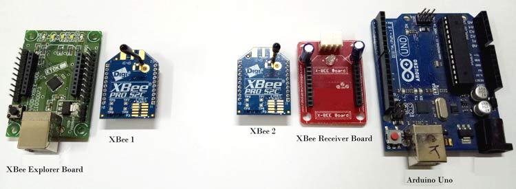
In previous tutorials we have learned about ZigBee protocol and its architecture, and also learned about wireless communication between two Xbee modules. Now in this tutorial we will interface XBee module with Arduino Uno board. The XBee connected with Arduino board will act as a receiver and it will communicate wirelessly with other XBee module which is serially connected with the laptop using a Explorer Board. So lets explore further for Arduino wireless communication using XBee.
Hardware Requirements
- 1 x Arduino Uno
- 2 x XBee Pro S2C modules (any other model can be used)
- 1 x Xbee explorer board (optional)
- 1 x Xbee Breakout board (optional)
- USB cables
- LEDs
Configuring XBee Modules using XCTU
As we have learnt in previous tutorials that the XBee module can act as a Coordinator, Router or an End device but it need to be configured to work in desired mode. So before using the XBee modules with Arduino, we have to configure these modules using XCTU software.
To connect XBee module with the laptop, a USB to serial converter or specifically designed explorer board is used. Just hook up the XBee module to the Explorer board and plug it with the laptop using USB cable.
If you don’t have any converter or explorer board, then an Arduino board can be used as a USB to serial device which can easily communicate with the XBee and laptop. Just upload blank sketch in Arduino board and now it can behave like a USB to Serial converter.
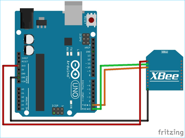
Connections for interfacing ZigBee module with Arduino are shown in the circuit diagram.

Connections:
- Tx (pin2)of XBee -> Tx of Arduino board
- Rx(pin3) of Xbee -> Rx of Arduino board
- Gnd(pin10) of Xbee -> GND of Arduino board
- Vcc (Pin1) of Xbee -> 3.3v of Arduino board
Here in this tutorial, a Explorer board is used to configure the XBee modules.
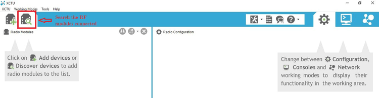
Download the XCTU software from this link and install it. After downloading and installing the XCTU software, open it and make sure your XBee module is properly connected. Check the COM port of the Arduino board in device manager.
Step 1:- Now, click on the search button. This will show you all the RF devices connected with your laptop. In our case, it will show only one XBee module.
Step 2:- Select the Serial port of the Explorer board/Arduino board and click on Next.

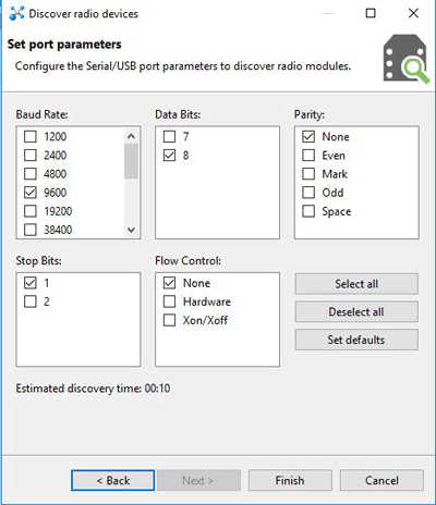
Step 3:- In the next window, set the USB port parameters as shown below and click on Finish.
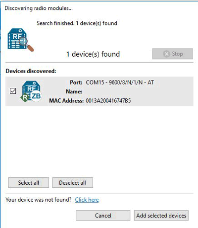
Step 4:- Select the Discovered device and click on Add selected device. This process will add your XBee module to XCTU dashboard.
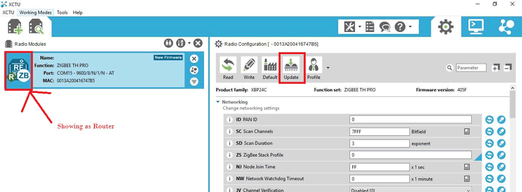
Step 5:- Now, you can configure your XBee module in this window. Use either AT commands or put the data manually. As you can see, there is R showing on the left panel which means Xbee is in router mode. We have to make it Coordinator for the transmitter part.
First, update the Firmware by clicking on the Update firmware.
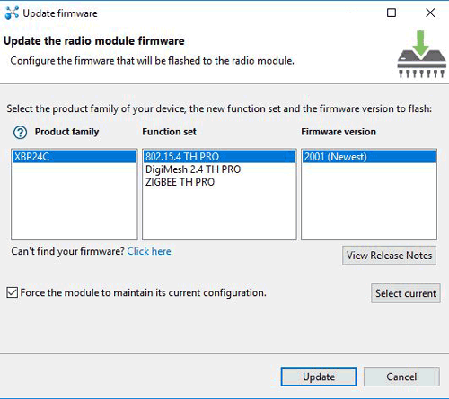
Step 6:- Choose the Product family of your device which is available on back of XBee module. Select function set and firmware version as highlighted below and click on Update.
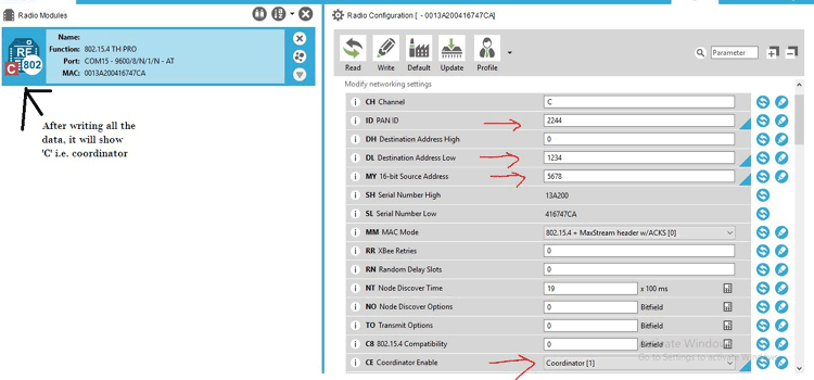
Step 7:- Now, you have to give ID, MY and DL data to make connection with other XBee. ID remain same for both the modules. Only MY and DL data interchange i.e. MY for the receiver XBee becomes DL of the transmitter XBee (coordinator) and DL for the receiver XBee becomes MY of the transmitter XBee. Make CE as Coordinator and then hit the Write button. As shown below.
|
|
ATDL |
ATMY |
ATID |
|
XBee 1 coordinator |
1234 |
5678 |
2244 |
|
XBee 2 end device |
5678 |
1234 |
2244 |
Step 8:- After writing the above data to the transmitter part, plug out it from the explorer board and plug it in the second XBee module. Repeat the same process as above only changes are the DL, MY, and CE. As we will make the second XBee as End device so in CE drop down menu, select the End device and hit the Write button.
Step 9:- Now, our XBee modules are ready to interface with the Arduino board. We will connect the transmitter XBee to the laptop and receiver XBee with the Arduino board. Then give commands to the receiver part using laptop.
Circuit Diagram for Receiver Part:
Connections:
- Tx (pin2)of XBee -> Rx of Arduino board
- Rx(pin3) of Xbee -> Tx of Arduino board
- Gnd(pin10) of Xbee -> GND of Arduino board
- Vcc (Pin1) of Xbee -> 3.3v of Arduino board
If you are using the Arduino board to connect the transmitter ZigBee with the laptop, connections will be same as for the programming the ZigBee.
Programming and Testing XBee communication using Arduino
Now, we will write a code for the receiver Arduino to switch ON the LED whenever receiver part receives ‘a’, and blink the LED whenever it receives ‘b’, for other characters LED will remain OFF.
Code is simple and easily understandable. We will just check the incoming characters using Serial.available() function and store this character in a variable using Serial.read(); function and match it with ‘a’ and ‘b’. If match is correct then perform the task specified in the condition. Complete code for Receiver part is given in the end. Upload the code in the Receiver part Arduino. Remove the Tx and Rx wires of XBee before uploading.
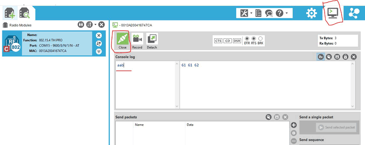
Now, we all set to test our transmitter and receiver. To give command to the transmitter part, we will use XCTU’s console terminal. Click on the Console icon near the settings option. Then, click on Open button to connect the XBee to the laptop.
Enter ‘a’ in Console log. You will see that LED will turn ON for 2 seconds and after that enter ‘b’ to make the led blink for 5 times.
You can also connect the transmitter XBee to the Arduino board, just change the receiver code little bit. In place of Serial.read() function, use Serial.println() function to send the characters.
Check the Demonstration Video given below.
This XBee-Arduino setup can be used to make many useful wireless applications like Home automation system, chatting room etc.
int led = 13;
int received = 0;
int i;
void setup() {
Serial.begin(9600);
pinMode(led, OUTPUT);
}
void loop() {
if (Serial.available() > 0) {
received = Serial.read();
if (received == 'a'){
digitalWrite(led, HIGH);
delay(2000);
digitalWrite(led, LOW);
}
else if (received == 'b'){
for(i=0;i<5;i++){
digitalWrite(led, HIGH);
delay(1000);
digitalWrite(led, LOW);
delay(1000);
}
}
}
}

Hi,
I found your article very helpful. I am doing same as you implemented in this article.
I have 1 Arduino UNO and 2 XBee Pro S3B modules and 1 XBee Shield. I have connected 1 XBee module(which is configured as Master) to sheild and another one (Slave) has connected to Arduino UNO.
If I send "a" or "b" letters from xctu then Led on arduino should blink. This is the working of my code.
In the receiver code, I have included XBee.h lib in Arduino. But it gives an error at XBee.begin(9600);
and all other functions of XBee like received = XBee.read();
error: expected unqualified-id before '.' token
I am a learner and I am using Arduino and XBee communication for the first time in my project.
Plz guide.
Thanks