

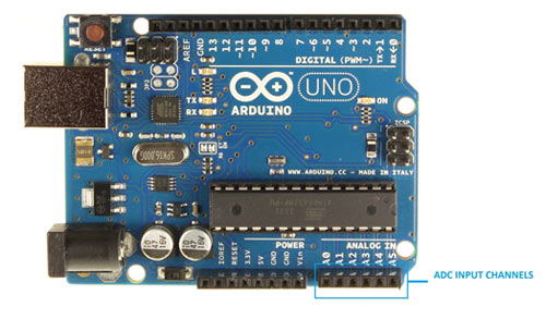
In this tutorial we are introducing concept of ADC (Analog to Digital Conversion) in ARDUINO UNO. Arduino board has six ADC channels, as show in figure below. Among those any one or all of them can be used as inputs for analog voltage. The Arduino Uno ADC is of 10 bit resolution (so the integer values from (0-(2^10) 1023)). This means that it will map input voltages between 0 and 5 volts into integer values between 0 and 1023. So for every (5/1024= 4.9mV) per unit.
In all of this we are going to connect a potentiometer or pot to the ‘A0’ channel, and we are going to show the ADC result on a simple display. The simple displays are 16x1 and 16x2 display units. The 16x1 display unit will have 16 characters and are in one line. The 16x2 will have 32 characters in total 16in 1st line and another 16 in 2nd line. Here one must understand that in each character there are 5x10=50 pixels so to display one character all 50 pixels must work together, but we need not have to worry about that because there a another controller (HD44780) in the display unit which does the job of controlling the pixels (you can see it in LCD unit, it is the black eye at the back).
Components Required
Hardware: ARDUINO UNO, power supply (5v), JHD_162ALCD (16x2LCD), 100uF capacitor, 100KΩ pot or potentiometer, 100nF capacitor.
Software: arduino IDE (Arduino nightly)
Circuit Diagram and Explanation
In 16x2 LCD there are 16 pins over all if there is a back light, if there is no back light there will be 14 pins. One can power or leave the back light pins. Now in the 14 pins there are 8 data pins (7-14 or D0-D7), 2 power supply pins (1&2 or VSS&VDD or GND&+5v), 3rd pin for contrast control (VEE-controls how thick the characters should be shown), and 3 control pins (RS&RW&E).
In the circuit, you can observe I have only took two control pins, the contrast bit and READ/WRITE are not often used so they can be shorted to ground. This puts LCD in highest contrast and read mode. We just need to control ENABLE and RS pins to send characters and data accordingly.
The connections which are done for LCD are given below:
PIN1 or VSS to ground
PIN2 or VDD or VCC to +5v power
PIN3 or VEE to ground (gives maximum contrast best for a beginner)
PIN4 or RS (Register Selection) to PIN8 of ARDUINO UNO
PIN5 or RW (Read/Write) to ground (puts LCD in read mode eases the communication for user)
PIN6 or E (Enable) to PIN9 of ARDUINO UNO
PIN11 or D4 to PIN10 of ARDUINO UNO
PIN12 or D5 to PIN11 of ARDUINO UNO
PIN13 or D6 to PIN12 of ARDUINO UNO
PIN14 or D7 to PIN13 of ARDUINO UNO
The ARDUINO IDE allows the user to use LCD in 4 bit mode. This type of communication enables the user to decrease the pin usage on ARDUINO, unlike other the ARDUINO need not be programmed separately for using it in 4 it mode because by default the ARDUINO is set up to communicate in 4 bit mode. In the circuit you can see we used 4bit communication (D4-D7).
So from mere observation from above table we are connecting 6 pins of LCD to controller in which 4 pins are data pins and 2 pins for control.

The above figure shows the circuit diagram of ADC of ARDUINO UNO.
Working
For interfacing an LCD to the ARDUINO UNO, we need to know a few things.
|
First of all the UNO ADC channels has a default reference value of 5V. This means we can give a maximum input voltage of 5V for ADC conversion at any input channel. Since some sensors provide voltages from 0-2.5V, with a 5V reference we get lesser accuracy, so we have a instruction that enables us to change this reference value. So for changing the reference value we have (“analogReference();”)
As default we get the maximum board ADC resolution which is 10bits, this resolution can be changed by using instruction (“analogReadResolution(bits);”). This resolution change can come in handy for some cases.
Now if the above conditions are set to default, we can read value from ADC of channel ‘0’ by directly calling function “analogRead(pin);”, here “pin” represents pin where we connected analog signal, in this case it would be “A0”. The value from ADC can be taken into an integer as “int ADCVALUE = analogRead(A0); ”, by this instruction the value after ADC gets stored in the integer “ADCVALUE”.
NOW let’s talk a bit about 16x2 LCD. First we need to enable the header file (‘#include <LiquidCrystal.h>’), this header file has instructions written in it, which enables the user to interface an LCD to UNO in 4 bit mode without any fuzz. With this header file we need not have to send data to LCD bit by bit, this will all be taken care of and we don’t have to write a program for sending data or a command to LCD bit by bit.
Second we need to tell the board which type of LCD we are using here. Since we have so many different types of LCD (like 20x4, 16x2, 16x1 etc.). In here we are going to interface a 16x2 LCD to the UNO so we get ‘lcd.begin(16, 2);’. For 16x1 we get ‘lcd.begin(16, 1);’.
In this instruction we are going to tell the board where we connected the pins, The pins which are connected are to be represented in order as “RS, En, D4, D5, D6, D7”. These pins are to be represented correctly. Since we connected RS to PIN0 and so on as show in circuit diagram, We represent the pin number to board as “LiquidCrystal lcd(0, 1, 8, 9, 10, 11);”.
After above there all there is left is to send data, the data which needs to be displayed in LCD should be written as “ cd.print("hello, world!");”. With this command the LCD displays ‘hello, world!’.
As you can see we need not worry about any this else, we just have to initialize and the UNO will be ready to display data. We don’t have to write a program loop to send the data BYTE by BYTE here.
Using ADC of Arduino Uno is explained step by step in C program given below.
#include <LiquidCrystal.h>
// initialize the library with the numbers of the interface pins
LiquidCrystal lcd(8, 9, 10, 11, 12, 13); // REGISTER SELECT PIN,ENABLE PIN,D4 PIN,D5 PIN, D6 PIN, D7 PIN
char ADCSHOW[5]; //initializing a character of size 5 for showing the ADC result
void setup()
{
// set up the LCD's number of columns and rows:
lcd.begin(16, 2);
}
void loop()
{
// set the cursor to column 0, line 1
lcd.print(" CIRCUIT DIGEST"); //print name
lcd.setCursor(0, 1); // set the cursor to column 0, line
lcd.print("ADC RESULT:"); //print name
String ADCVALUE = String(analogRead(A0)); //intailizing a string and storing ADC value in it
ADCVALUE.toCharArray(ADCSHOW, 5); // convert the reading to a char array
lcd.print(ADCSHOW); //showing character of ADCSHOW
lcd.print(" ");
lcd.setCursor(0, 0); // set the cursor to column 0, line1
}
Comments
Great little technique...
Great little technique... thanks.
Is it possible though to display a range from say 0 - 100 rather than 0 - 1024?
if i need to add the voltage
if i need to add the voltage value along with the adc value in the display board, what will i need to modify in the program?

Thanks for posting such circuit ..
Really i got exactally i want to my project..
Thanku