

In this project we will develop a tone generator using Arduino Uno. We will have buttons interfaced with the UNO and each one of them generates different intensity of tone. The frequency of tone generated by the UNO is same at every internal. It’s the intensity of the sound which changes with each press. This is the one of the easiest way to make a piano with Arduino Uno. Also check this Piano circuit.
The tones can be increased up to 20. This gives the best tone variation and much smoother changes. The intensity of the tone is changed by PWM (Pulse Width Modulation). An example of PWM is shown in below graph.
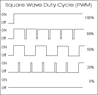
In PWM, the frequency of signal or the time period of signal (Ton + Toff) is always constant. Only the ratio of TURN ON and TURN OFF time changes. For example in the second graph in above figure, the TURN ON time is 80% and TURN OFF time is 20% of complete duration.
In the third graph, the TURN ON time is 50% and TURN OFF time is 50% of complete duration. So in first case we have a duty ratio of 80% and in second case we have a duty ratio of 20%.
With this change in duty ratio we have a change in Vrms (Root Mean Square value of Voltage), when this voltage is given to the buzzer it makes a different noise whenever there is a change in duty ratio.
We are going to program the UNO to provide a PWM signal of different duty ratio for each of buttons. So we have a tone generator at hand which generates a different tone with each button press.
Components Required
Hardware: Arduino Uno, Power supply (5v), 1000 uF capacitor, 100 nF capacitor, Buzzer, buttons (8 pieces).
Software: AURDINO nightly or Atmel studio 6.2
Circuit Diagram and Working Explanation
The circuit for tone generator is shown in below diagram.

To filter out the noise from supply voltage capacitors are placed across terminals as shown in the diagram.
The PWM of Arduino Uno can achieved at any of pins symbolized as “ ~ ” on the PCB board. There are six PWM channels in UNO. However we cannot use PWM pins established over the PINS 0-7, as the PINS are preferred for buttons interface.
There is a reason for selecting PINS 0-7 as inputs, because the PINS 0-7 represent the PORTD of microcontroller. So in the latter case we can take the complete BYTE of PORTD.
Now for getting a different duty ratio PWM, we are going to use following command.
analogWrite(9,VALUE); |
From above condition we can directly get the PWM signal at the corresponding pin. The first parameter in brackets is for choosing the pin number of PWM signal. Second parameter is for writing duty ratio.
The PWM value of Arduino Uno can be changed from 0 to 255. With “0” as lowest to “255” as highest. With 255 as duty ratio we will get 5V at PIN9. If the duty ratio is given as 125 we will get 2.5V at PIN9. We are going to divide the duty ratio of 0-250 among 8 buttons interfaced at PORTD of UNO. Here I choose 25 increments for every button, but it is of your choice.
With that we will have a PWM signal whose duty ratio changes with each button. This being given to buzzer, we have tone generator. Working of this Arduino based tone generator is explained step by step in C code given below.
Complete Project Code
void setup()
{
                for (int i=0;i<8;i++)
                {
                pinMode(i, INPUT_PULLUP);//take pins0-7 as inputs with default high or pulled up pins.
                }
                pinMode(9,OUTPUT);//buzzer output at pin9
}

// the loop routine runs over and over again forever:
void loop()
{
                if (digitalRead(0)==LOW)
                {
                                analogWrite(9,25);//if button 1 is pressed PWM of duty ratio(25*100)/255 is given to buzzer
                                delay(100);
                                analogWrite(9,0);
                }
                if (digitalRead(1)==LOW)
                {
                                analogWrite(9,50); //if button 2 is pressed PWM of duty ratio(50*100)/255 is given to buzzer

                                delay(100);
                                analogWrite(9,0);
                }
                if (digitalRead(2)==LOW)
                {
                                analogWrite(9,75);// /if button 3 is pressed PWM of duty ratio(75*100)/255 is given to buzzer

                                delay(100);
                                analogWrite(9,0);
                }
                if (digitalRead(3)==LOW)
                {
                                analogWrite(9,100); /if button 4 is pressed PWM of duty ratio(100*100)/255 is given to buzzer

                                delay(100);
                                analogWrite(9,0);
                }
                if (digitalRead(4)==LOW)
                {
                                analogWrite(9,125);
                                delay(100);
                                analogWrite(9,0);
                }
                if (digitalRead(5)==LOW)
                {
                                analogWrite(9,150);
                                delay(100);
                                analogWrite(9,0);
                }
                if (digitalRead(6)==LOW)
                {
                                analogWrite(9,175);
                                delay(100);
                                analogWrite(9,0);
                }
                if (digitalRead(7)==LOW)
                {
                                analogWrite(9,200);
                                delay(100);
                                analogWrite(9,0);
                }
}
