
Infrared sensors are much common in our electronics life. They are used in many real time applications like for opening and closing the gates at Metro Station. Even they are used in our Mobile phone to turn off the display light during the call.
IR sensor is very popular sensor, which is frequently used in many applications in electronics, like it is used in Remote control system, motion detector, Product counter, Line follower Robots, Alarms etc. We have already covered complete working of IR sensor here in this article: IR Sensor Module Circuit. IR Sensor basically consists a IR LED and a Photodiode.
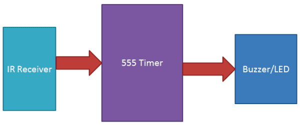
In this circuit, we are going to demonstrate an application related to IR sensors which is IR Detection using 555 Timer IC. Here we have used IR LED or TV/DVD remote as a IR transmitter and Photo Diode as IR Receiver to detect the IR signal. Detection of IR signal will Trigger the 555 timer and buzzer will start beeping. Almost same concept has already been covered in our previous circuit: IR Based Security Alarm, where we used voltage comparator IC LM358, in place to transistor, to trigger the 555 IC.
Required Components:
- 555 Timer IC
- BC547 transistor
- BC557 transistor
- IR LED or TV/DVD Remote
- IR receiver or Photo diode
- 10K resistor
- 1K resistor
- 22K resistor
- Buzzer
- LED
- Power supply 5 Volt
- 10 uF capacitor
- 220 Ohm resistor
- Bread board
Circuit and Working Explanation:
Before going into the explanation, we should note that Transistor Q1 BC547 is a NPN transistor, which conducts or Turns On, when a small positive voltage is applied to its base. And Transistor BC557 is PNP transistor which Conducts or Turns On, when a negative voltage (or ground) is applied to its base. Circuit of this IR detector is given below:

When the IR Sensor Circuit is switched ON, IR LED starts emitting the Infrared, which falls upon the photodiode and a potential difference is generated across PHOTO diode which Turns On the transistor BC547, which further Turns On the Transistor BC557 by pulling down its base to Ground. Now Transistor BC557 starts conducting and power supply is applied to the 555 Timer IC (at PIN 8), which turns ON the 555 IC. 555 Timer IC is configured in Astable Mode, so the LED and buzzer, which are connected to its Output (PIN 3), start blinking and beeping, with a particular frequency. This frequency of LED blinking can be determined by the given formulae of Astable Multvibrator:
F = 1.44 / (R1+2*R2) * C1
Where R1 represents the resistor between Pin 7 & Pin 8 and R2 represents the resistor between Pin 6 & Pin 7. C1 is capacitor between Pin 6 and Ground of 555 Timer IC. R (resistance) is in ohm and C (capacitance) is in farads.
We can also use TV/DVD remote for IR radiation (replacing the IR LED), as you can check in the Video at the end.
555 Timer IC is here generating some variable frequency. 555 Timer IC is a general purpose IC which can be configured in some different modes like A-stable, Mono-stable, Bi-stable, having different applications for each mode. Here in this project we have configured 555 Timer as an A-stable multi-vibrator in which both the stage of signal are unstable. Astable mode is also called frequency generator.
To detect or read the IR light, we can also use TSOP1738 as IR Receiver, its output is active low, means output remains High when there is no IR, and becomes low when it detects IR, you can check IR Transmitter and Receiver using TSOP.
Comments
Answer
no you cant use regular LED instead of IR LED . Cause the frequency is not the same at all . also there are some quite differences . and if you use 1uF instead of 10uF then the stability will be change of this circuit whether it is on astable or monostable mode ..
what changes I have to made
what changes I have to made in a circuit to blink second led when there is some obstacle between IR emitter and IR detector
my circuit is not working
my circuit is not working despite of doing all correct connections and why 10 resistors have been used in the circuit made on the breadboard instead of using 7 resistors as shown in the circuit diagram.

Can I use a 1uf capacitor instead of 10uf? And the Photodiode is place in the IR right? And the Photodiode is facing a regular LED?